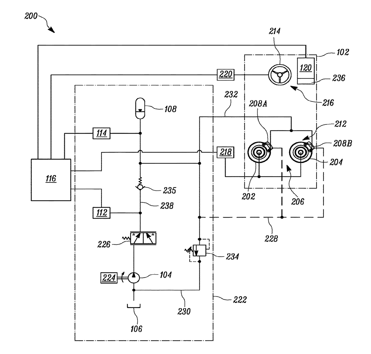
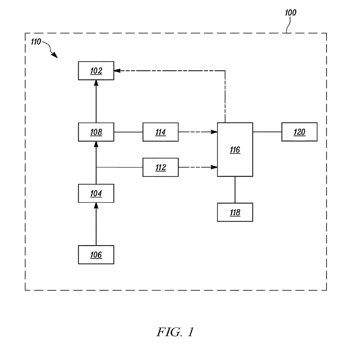
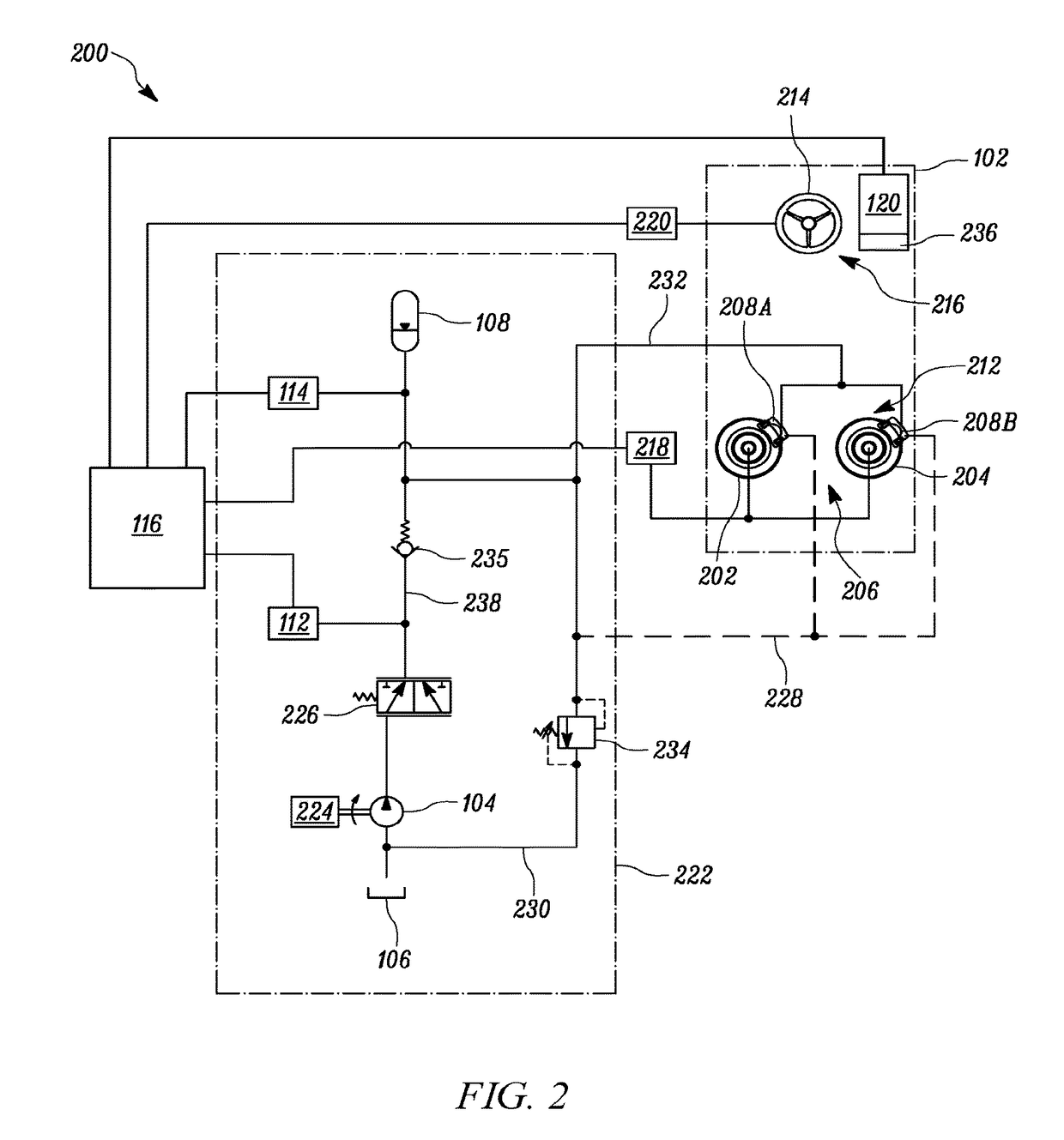
Systems, apparatuses, and methods for monitoring pressure in a hydraulic system

a hydraulic system and pressure monitoring technology, applied in the field of hydraulic systems, can solve problems such as hydraulic pressure characteristics deviating from acceptable limits, loss of pressure,

Active Publication Date: 2018-01-04
CATERPILLAR INC
View PDF0 Cites 3 Cited by
  • Summary
  • Abstract
  • Description
  • Claims
  • Application Information

AI Technical Summary

Problems solved by technology

However, each instance of manual pressure gauge connection can cause loss of pressure.
As such, periodic connections of pressure gauges to hydraulic systems, over time, can cause hydraulic pressure characteristics to deviate from acceptable limits.

Method used


Image

  • Systems, apparatuses, and methods for monitoring pressure in a hydraulic system
  • Systems, apparatuses, and methods for monitoring pressure in a hydraulic system
  • Systems, apparatuses, and methods for monitoring pressure in a hydraulic system

Examples


Embodiment Construction

[0014]The description set forth below in connection with the appended drawings is intended as a description of various embodiments of the described subject matter and is not necessarily intended to represent the only embodiment(s). In certain instances, the description includes specific details for the purpose of providing an understanding of the described subject matter. However, it will be apparent to those skilled in the art that embodiments may be practiced without these specific details. In some instances, well-known structures and components may be shown in block diagram form in order to avoid obscuring the concepts of the described subject matter. Wherever possible, the same reference numbers will be used throughout the drawings to refer to the same or the like parts.

[0015]Any reference in the specification to “one embodiment” or “an embodiment” means that a particular feature, structure, characteristic, operation, or function described in connection with an embodiment is inc...


PUM


Abstract

A method, system, and apparatus to determine a malfunction or an abnormal pressure condition in a hydraulic system over a time period are provided. The method, system, and apparatus include monitoring hydraulic accumulator charge time, hydraulic accumulator discharge time, and hydraulic pump pressure over the time period, and determining whether the monitored hydraulic accumulator charge time, hydraulic accumulator discharge time, and hydraulic pump pressure are within respective predetermined ranges. A maintenance notification is output responsive to at least one of the monitored hydraulic accumulator charge time, hydraulic accumulator discharge time, and hydraulic pump pressure being outside the respective predetermined ranges during the time period.

Description

TECHNICAL FIELD[0001]The present disclosure relates to hydraulic systems, and more particularly to systems, apparatuses, and methods for monitoring pressure in hydraulic systems.BACKGROUND[0002]Machines, such as off-highway trucks and mining trucks, may employ one or more hydraulic systems to control various operations. For example, a hydraulic braking system can be employed to control driving speed of the machine, and a hydraulic pump can be employed to charge a hydraulic braking accumulator or accumulators of the hydraulic braking system. Similarly, a hydraulic steering system can be employed to steer the machine, and a hydraulic pump can be employed to charge a hydraulic steering accumulator or accumulators of the hydraulic steering system. Since such hydraulic systems operate with fluid, such as Nitrogen for an accumulator and oil for a hydraulic pump, maintenance activities may be carried out on the hydraulic systems to identify whether pressures of the hydraulic system and com...

Claims


Application Information

Patent Timeline
Patent Type & Authority Applications(United States)
IPC IPC(8): G07C5/08B60T13/14B60K17/10B60T17/22G07C5/00B62D5/06
CPCG07C5/0808G07C5/006B60K17/10B60T2270/88B60T13/14B60T17/221B62D5/06B60T13/662
Inventor MILTON, DALE E.DHORAJIYA, ANKITKUMAR P.
Owner CATERPILLAR INC
Why Eureka
Try Eureka