Conformal broadband directional 1/2 flared notch radiator antenna array

a radiator antenna array, a broadband technology, applied in the direction of antennas, antenna details, antenna adaptation in movable bodies, etc., can solve the problems of poor radiation in the forward direction, limited field of view, and inability to enhance the forward radiation of the forward radiation

Active Publication Date: 2018-01-11
RAYTHEON CO
View PDF0 Cites 17 Cited by
  • Summary
  • Abstract
  • Description
  • Claims
  • Application Information

AI Technical Summary

Benefits of technology

[0006]The following is a summary of the invention in order to provide a basic understanding of some aspects of the invention. This summary is not intended to identify key or critical elements of the invention or to

Problems solved by technology

These antennas are narrow band (e.g., a few % of the center frequency), and because of their physical and/or electrical characteristics they can not be inclined to enhance their forward radiation.
The result is a limited field of view.
Conventional conformal mounting situates the antenna elements so they face normal to the missile surface resulting in poor radiation in the forward direction.
This makes radiat

Method used


Image

  • Conformal broadband directional 1/2 flared notch radiator antenna array
  • Conformal broadband directional 1/2 flared notch radiator antenna array
  • Conformal broadband directional 1/2 flared notch radiator antenna array

Examples


Embodiment Construction

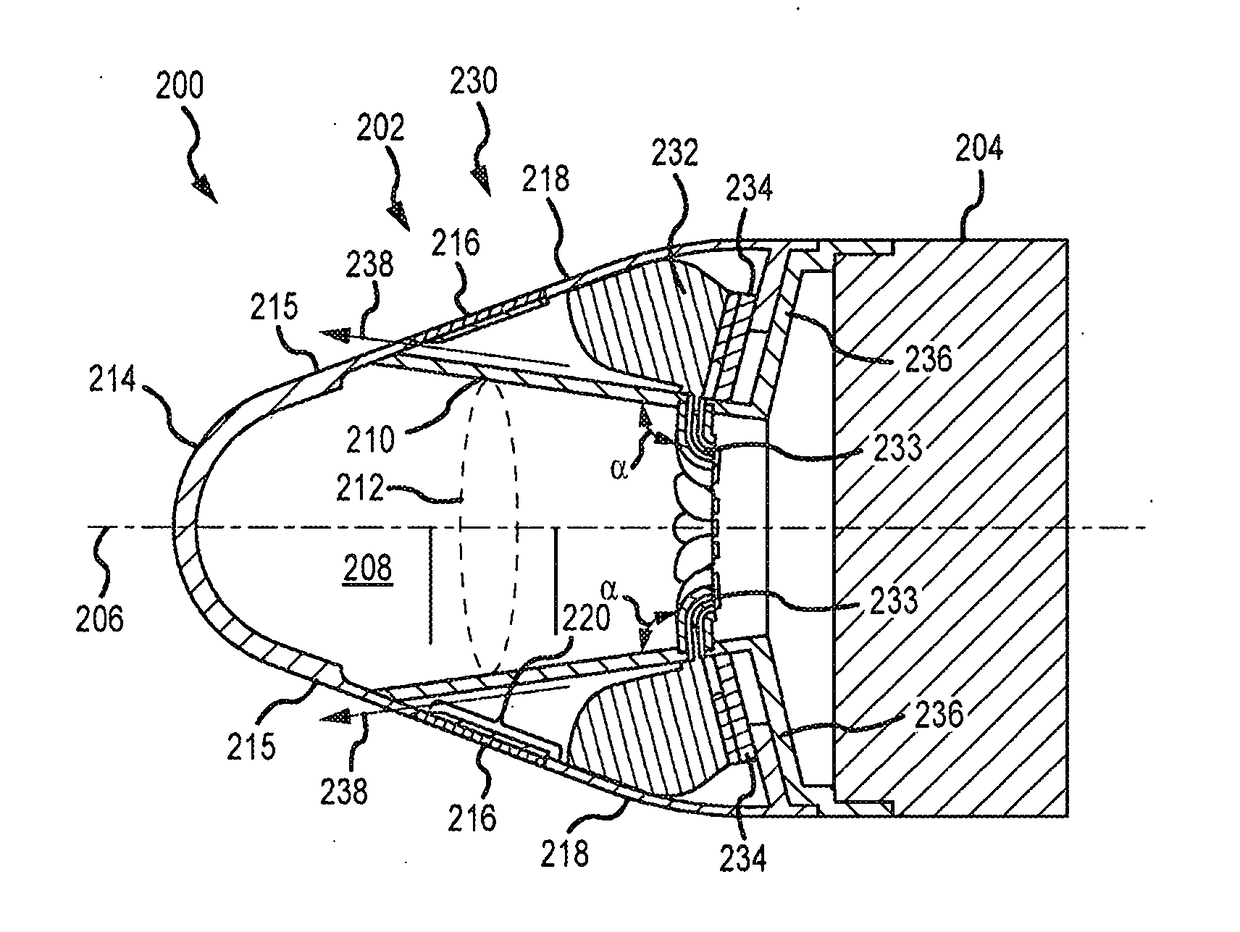
[0023]The present invention describes a conformal broadband directional antenna array for a missile that is more compact and exhibits a more desirable forward radiation pattern inclined towards boresight than the inclined slotline antenna array described in U.S. Pat. No. 4,220,330. Additional embodiments further improve the directionality and isolation of adjacent antenna elements. In addition, one or more antenna elements may be configured to launch RF energy backwards inclined towards a longitudinal axis of the missile to form, for example, a data link.

[0024]The antenna elements are configured to send and receive “broadband” RF energy. Broadband is defined to mean a bandwidth of at least 100% of the center frequency, and more typically at least 3-to-1. The bandwidth occupies a portion of the spectrum from 50 MHz to 100 GHz, and typically within 100 MHz to 50 GHz. For example, an antenna array may be designed for 1-20 GHz or for 20-40 GHz.

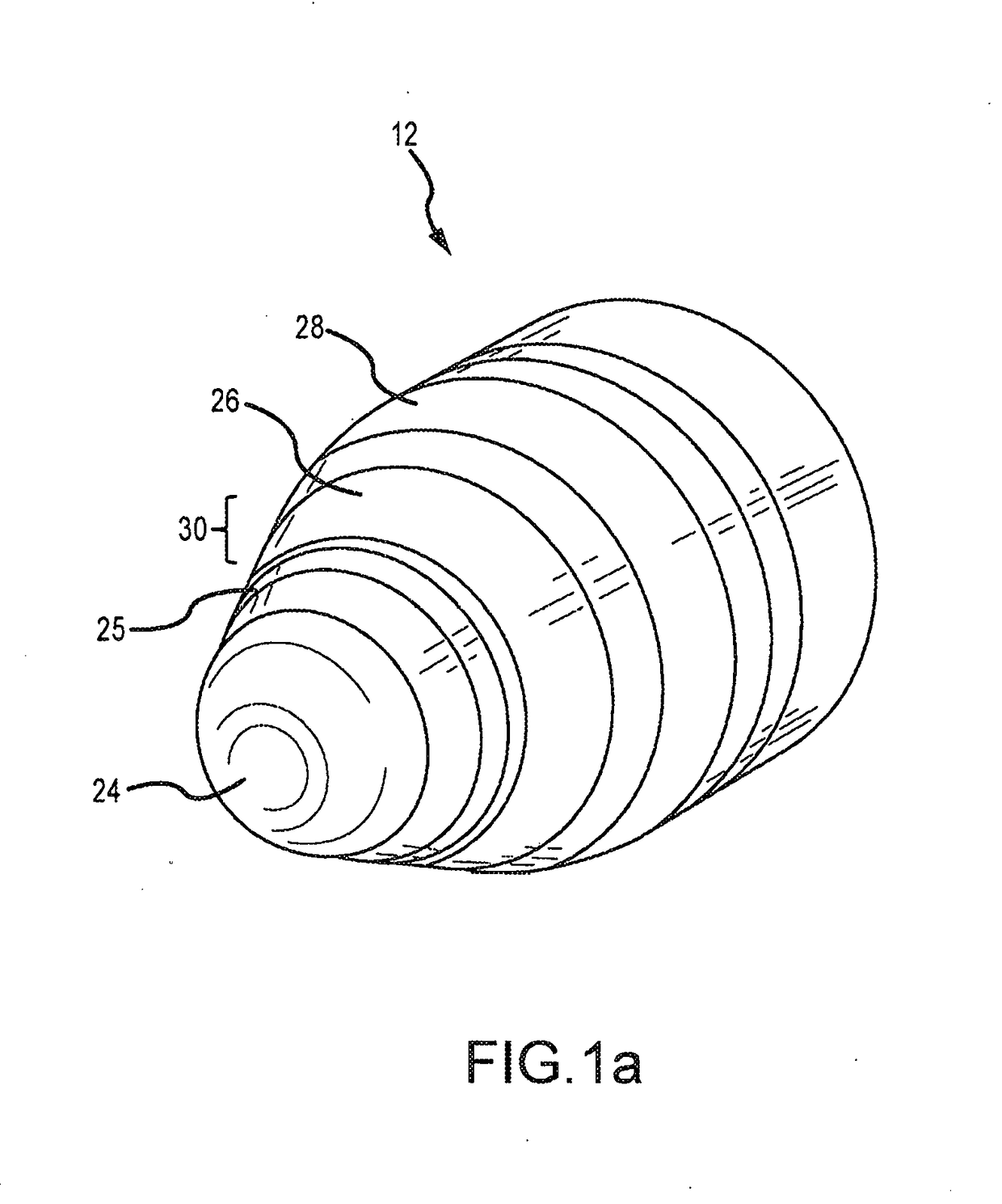
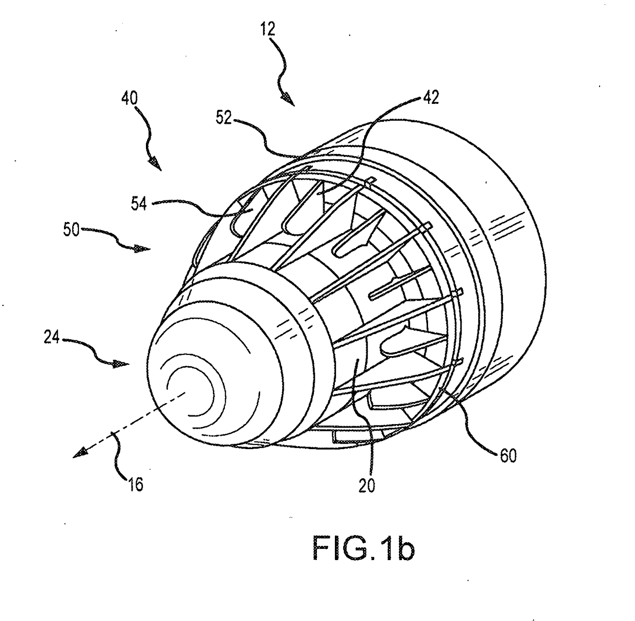
[0025]Referring now to FIGS. 1a through 1d,...


PUM


Abstract

An antenna array includes a plurality of ½ flared notch radiators recessed within a missile nose cone and positioned in a circumferential arrangement around and extending radially from the payload's metal skin to contact an annular metal cover that provides a ground plane such that each ½ flared notch radiator is inclined towards the boresight axis. The payload's metal skin provides an image plane for each ½ flared notch radiator to launch RF energy with a radial polarization normal to the image plane forward through the annular RF radome. Each ½ flared notch radiator may be positioned within a 5½ sided waveguide to further improve directionality and isolation.

Description

BACKGROUND OF THE INVENTIONField of the Invention[0001]The present invention relates to antenna arrays, and more particularly to conformal broadband directional antenna arrays useful for missile nose cones.Description of the Related Art[0002]U.S. Pat. No. 5,023,623, entitled “Dual Mode Antenna Apparatus Having Slotted Waveguide and Broadband Arrays,” by Donald E. Kreinheder et al., the entire contents of which are incorporated herein by this reference, provides a description of conventional missile target detection and tracking systems. Briefly, one type of target tracking system is known as broadband anti-radiation homing (ARH). Such a system is passive, and tracks a target by receiving radiation emitted by the target.[0003]Known conformal arrays for missiles employ conformal slot radiators and microstrip patch radiators. See Min Liu et al., “A 35 GHz Cone Conformal Microstrip 4×4 array” Proc. Of Asia-Pacific Microwave Conf. 2007 and D. Augustin et al., “Performance of an Original ...

Claims


Application Information

Patent Timeline
IPC IPC(8): H01Q13/02H01Q1/28H01Q1/42H01Q1/52
CPCH01Q13/0208H01Q1/281H01Q1/42H01Q1/523H01Q1/286H01Q13/085H01Q21/205
Inventor WANGSVICK, CHAD
Owner RAYTHEON CO
Why Eureka
Try Eureka