Abatement device

a technology of a device and a filter body, which is applied in the direction of final product manufacturing, sustainable manufacturing/processing, and separation processes, can solve the problems of a drainage process of circulating water that requires considerable costs, and achieve the effect of reducing the average drainage flow

Active Publication Date: 2018-01-18
EDWARDS JAPAN
View PDF2 Cites 1 Cited by
  • Summary
  • Abstract
  • Description
  • Claims
  • Application Information

AI Technical Summary

Benefits of technology

[0006]The present invention has been made in view of such a conventional task, and an object is to provide an abatement device that reduces an amount of drainage of circulating water.
[0008]With this configuration, the average drainage flow of the circulating water can be reduced, since the average drainage flow of the circulating water is lowered to the low flow while inhibiting volatilization of hydrogen fluoride within the circulating water, when hydrofluorosilicic acid can be produced with silicon dioxide and hydrogen fluoride.
[0010]With this configuration, the average drainage flow of the circulating water can be reduced, even when process gas does not flow into the abatement device, such as when a process chamber is to be cleaned within, since whether hydrofluorosilicic acid can be produced can be determined on the basis of the concentration of silicon dioxide remaining within the abatement device.
[0012]With this configuration, the average drainage flow of the circulating water can be reduced, even when cleaning gas does not flow into the abatement device in a CVD process or the like, since whether hydrofluorosilicic acid can be produced can be determined on the basis of the concentration of hydrogen fluoride remaining within the abatement device.
[0016]With this configuration, the abatement device can be made inexpensive, maintenance-friendly, and to continue to operate over a long period, since the acidity of the circulating water is determined on the basis of the concentration of hydrogen fluoride measured by the conductivity sensor.
[0019]The present invention can reduce the average drainage flow, since volatilization of hydrogen fluoride within the circulating water is inhibited even with the average drainage flow of the circulating water lowered to the low flow, when hydrofluorosilicic acid can be produced with silicon dioxide and hydrogen fluoride.

Problems solved by technology

There has been a problem that considerable costs are required for a drainage process of the circulating water.

Method used


Image

  • Abatement device
  • Abatement device
  • Abatement device

Examples


embodiments

[0024]An abatement device according to one embodiment of the present invention will be described below with reference to the drawings. Hereinafter, words “upper” and “lower” correspond to above and below in an up-down direction.

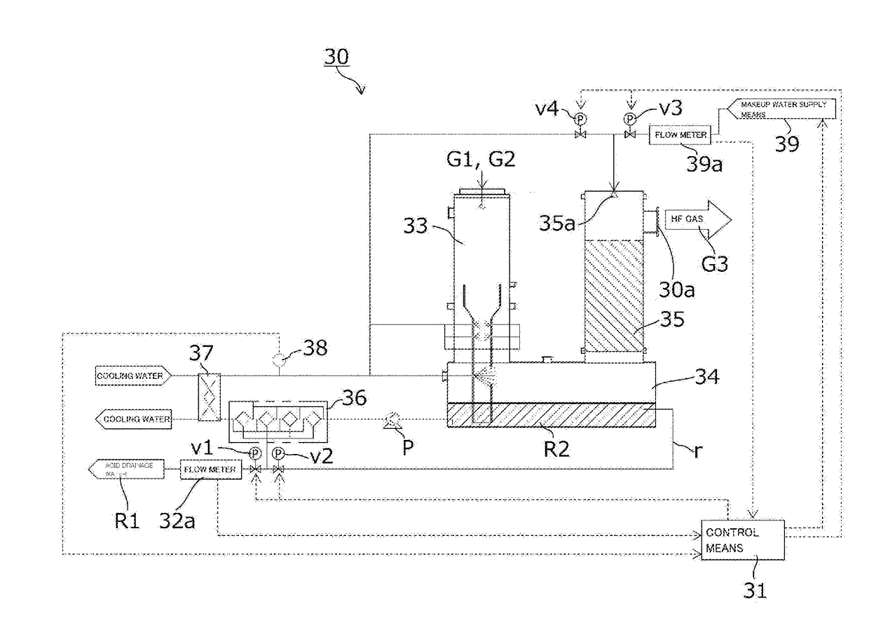
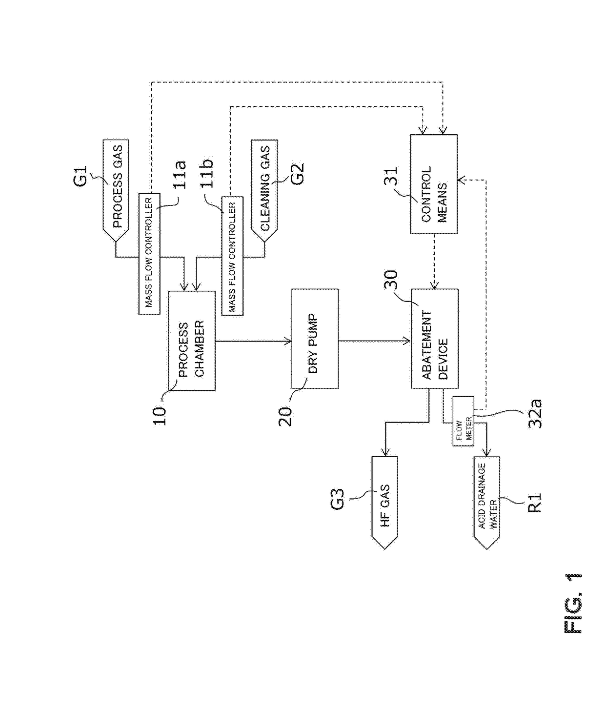
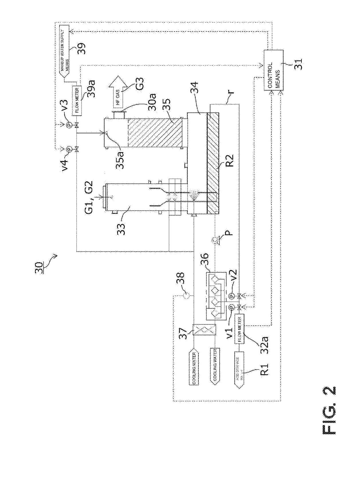
[0025]FIG. 1 is a diagram showing connections of a process chamber 10, a dry pump 20, and an abatement device 30.

[0026]The process chamber 10 is a part of a semiconductor manufacturing device, not shown. By performing a CVD process of causing deposition of a thin film on a surface of a semiconductor wafer, not shown, arranged within the process chamber 10, a device is obtained. In FIG. 1, one process chamber is connected to one abatement device. However, a plurality of process chambers may be connected to one abatement device.

[0027]Within the process chamber 10, process gas G1 containing silicon is supplied. The process gas G1 is supplied as a reactant for the CVD process within the process chamber 10. The process gas G1 supplied to the process chamber 10 is ...


PUM

PropertyMeasurementUnit
temperatureaaaaaaaaaa
concentrationaaaaaaaaaa
acidityaaaaaaaaaa

Abstract

Provided is an abatement device that reduces an amount of drainage of circulating water. The abatement device lowers an average drainage flow of circulating water to a low flow, when a ratio of a concentration of silicon dioxide within the circulating water and a concentration of hydrogen fluoride within the circulating water is greater than or equal to a predetermined value at which hydrofluorosilicic acid can be produced, and raises the average drainage flow of the circulating water to a high flow higher than the low flow, when the ratio of the concentration of silicon dioxide within the circulating water and the concentration of hydrogen fluoride within the circulating water is less than the predetermined value.

Description

BACKGROUND OF THE INVENTION1. Field of the Invention[0001]The present invention relates to an abatement device, particularly to an abatement device that processes process gas containing silicon and cleaning gas containing fluorine.2. Description of the Related Art[0002]In semiconductor manufacturing devices, liquid crystal panel manufacturing devices, solar cell manufacturing devices, and the like, process gas containing silicon (Si) and cleaning gas containing fluorine (F) are used. For example, in a semiconductor manufacturing process, process gas, e.g., monosilane (SiH4), is introduced into a process chamber upon performing, for example, a chemical vapor deposition (CVD) process in which an insulator, a metal film, or the like is deposited on a semiconductor wafer to form a film using a chemical vapor reaction.[0003]Upon removing a product adhering within the process chamber, cleaning gas, such as nitrogen trifluoride (NF3), in accordance with the type of product is regularly int...

Claims


Application Information

Patent Timeline
Patent Type & Authority Applications(United States)
IPC IPC(8): B01D53/96B01D53/68C23C16/52B01D21/26B01D47/14C23C16/44
CPCB01D53/96B01D21/267B01D53/68B01D47/14C23C16/4412C23C16/52B01D2252/103B01D2257/2047B01D21/26B01D53/40H01L21/31B01D53/346B01D53/78B01D2257/553B01D2258/0216Y02P70/50Y02C20/30
Inventor YAMADA, TOSHIKIPOPE, ALEXANDER MICHAELBENNETT, ALISTAIRBARLOW, STEVENJONES, CHRISTOPHER PETER
Owner EDWARDS JAPAN
Why Eureka
Try Eureka