
Fuel deoxygenation systems

a fuel degassing and fuel technology, applied in the direction of liquid degassing, liquid degassing by filtration, separation process, etc., can solve the problems of difficult combustor relight at altitude, inefficient gas transport through liquid media to reach membranes, and large power-intensive membrane units for liquid degassing

Active Publication Date: 2018-01-18
HAMILTON SUNDSTRAND CORP
View PDF0 Cites 24 Cited by
  • Summary
  • Abstract
  • Description
  • Claims
  • Application Information

AI Technical Summary

Benefits of technology

The patent describes a system and method for deoxygenating fuel in an aircraft. The system includes a hydrocarbon recycler that recycling hydrocarbon vapor into fuel, a membrane that separates hydrocarbons from oxygen, and a sparging gas supply to remove oxygen from the fuel tank. The method involves sparging the fuel tank with nitrogen or other inert gas to remove oxygen, separating the sparging gas from the fuel tank, and recirculating the hydrocarbons back into the tank. The technical effects of this system and method include improving fuel quality, reducing the risk of fuel tank explosions, and increasing fuel tank safety.

Problems solved by technology

Membrane-based oxygen removal from liquid fuel suffers from inefficient gas transport through liquid media to reach membranes.
As a result, membrane units for liquid degassing tend to be large and power-intensive.
This can make combustor relight at altitude difficult, for example.
Also, sparging gas is not readily available on conventional aircraft.
Conventional methods have been unsatisfactory for on-board fuel deoxygenation.
Liquid fuel de-oxygenation systems that utilize membranes have been too large to be practical on aircraft.

Method used


Image

  • Fuel deoxygenation systems
  • Fuel deoxygenation systems
  • Fuel deoxygenation systems

Examples


Embodiment Construction

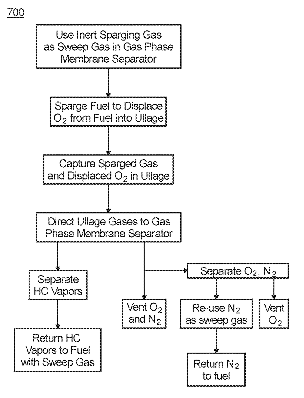
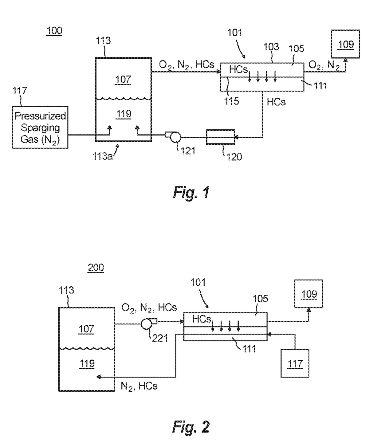
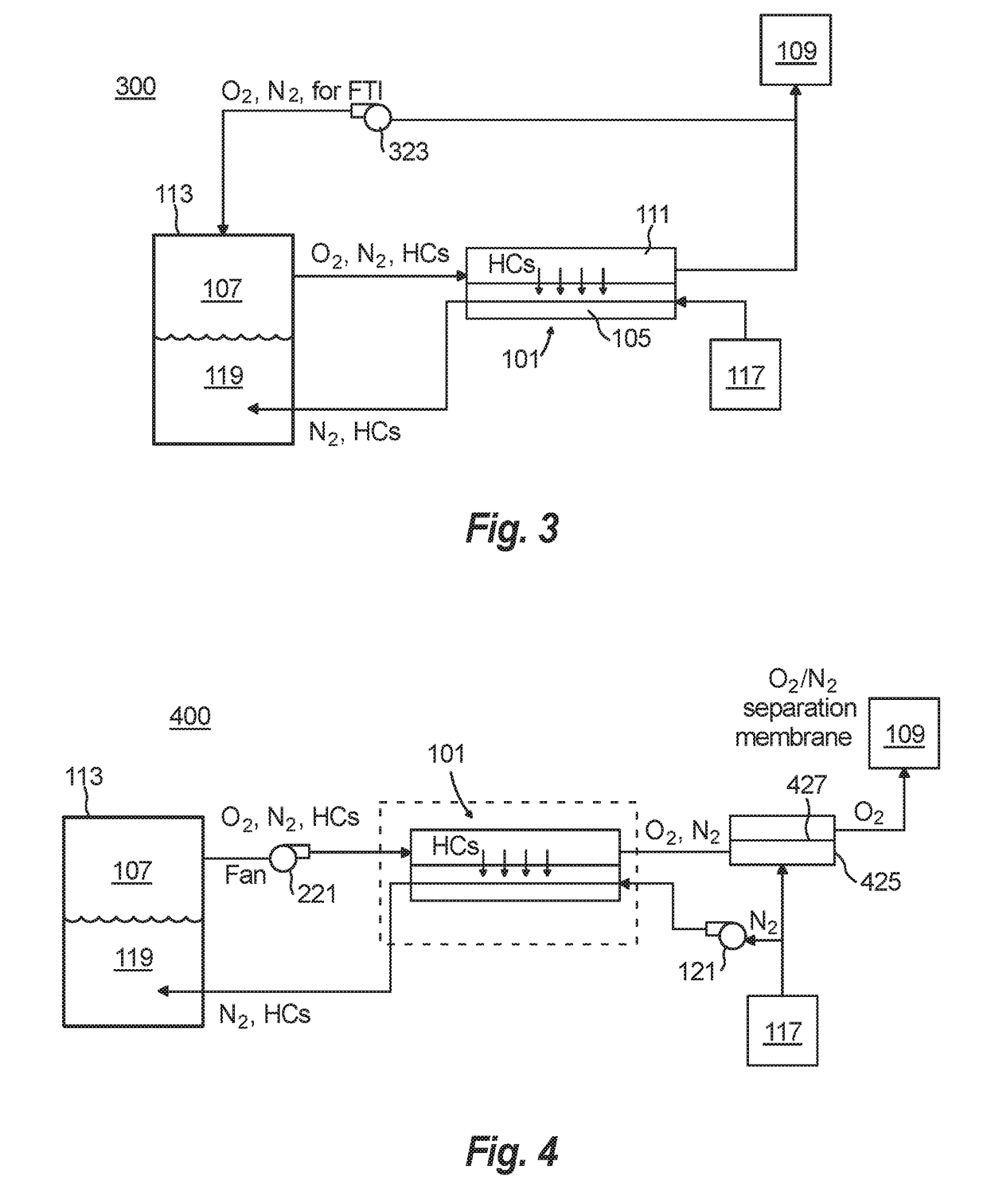
[0023]Reference will now be made to the drawings wherein like reference numerals identify similar structural features or aspects of the subject disclosure. For purposes of explanation and illustration, and not limitation, an illustrative view of an embodiment of a system in accordance with the disclosure is shown in FIG. 1 and is designated generally by reference character 100. Other embodiments and / or aspects of this disclosure are shown in FIGS. 2-7. The systems and methods described herein can be used to deoxygenate fuel while returning lost hydrocarbons to the fuel to prevent change in fuel composition and engine performance.

[0024]Referring to FIG. 1, a fuel deoxygenation system 100 for an aircraft includes a hydrocarbon recycler 101 configured to recycle hydrocarbon vapor into liquid fuel. The recirculated hydrocarbon vapors may condense in the liquid fuel. The hydrocarbon recycler 101 includes a housing 103 that partially defines an ullage channel 105 configured to fluidly com...


PUM

PropertyMeasurementUnit
Permeabilityaaaaaaaaaa
Permeation propertiesaaaaaaaaaa

Abstract

A fuel deoxygenation system for an aircraft includes a hydrocarbon recycler configured to recycle hydrocarbon gas into fuel. The hydrocarbon recycler includes a housing that partially defines an ullage channel configured to fluidly communicate with both an ullage of an aircraft fuel tank and a vent, wherein the housing partially defines a hydrocarbon recirculation channel configured to fluidly communicate with a liquid portion of a fuel tank. The hydrocarbon recycler also includes a membrane defining a sealing wall between the ullage channel and the hydrocarbon recirculation channel such that the membrane is in fluid communication with both the ullage channel and the hydrocarbon recirculation channel, wherein the membrane is configured to be permeable to hydrocarbons such that hydrocarbons in the ullage channel can pass through the membrane to the hydrocarbon recirculation channel and oxygen in the ullage channel to passes through to be vented.

Description

BACKGROUND1. Field[0001]The present disclosure relates to heat engines, more specifically to fuel deoxygenation systems (e.g., for jet fuel).2. Description of Related Art[0002]Dissolved oxygen is typically present in kerosene-based fuel at a concentration of approximately 70 ppm. Fuel stabilization by removal of oxygen avoids formation of carbonaceous deposits at elevated fuel temperatures and enables higher capability thermal management of engine accessories. Conventional methods to deoxygenate fuel have deficiencies. Membrane-based oxygen removal from liquid fuel suffers from inefficient gas transport through liquid media to reach membranes. As a result, membrane units for liquid degassing tend to be large and power-intensive.[0003]Sparging (displacement of dissolved oxygen by bubbling nitrogen through fuel) has the undesired effect of removing lighter hydrocarbons which physically alters the fuel composition. This can make combustor relight at altitude difficult, for example. Als...

Claims


Application Information

Patent Timeline
IPC IPC(8): B64D37/34B01D19/00B64D37/32
CPCB64D37/34B01D19/0005B01D19/0031B64D37/32Y02T50/40
Inventor RHEAUME, JONATHANCORDATOS, HARALAMBOS
Owner HAMILTON SUNDSTRAND CORP
Learn More