Gas sensor element
- Summary
- Abstract
- Description
- Claims
- Application Information
AI Technical Summary
Benefits of technology
Problems solved by technology
Method used
Image

Examples
Embodiment Construction
[0032]Hereinafter, Embodiments 1 and 2 of the gas sensor element of the present invention will be described with reference to the drawings. (Embodiments 1 and 2 of gas sensor element)
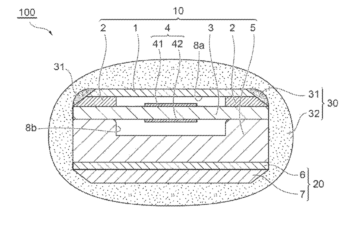
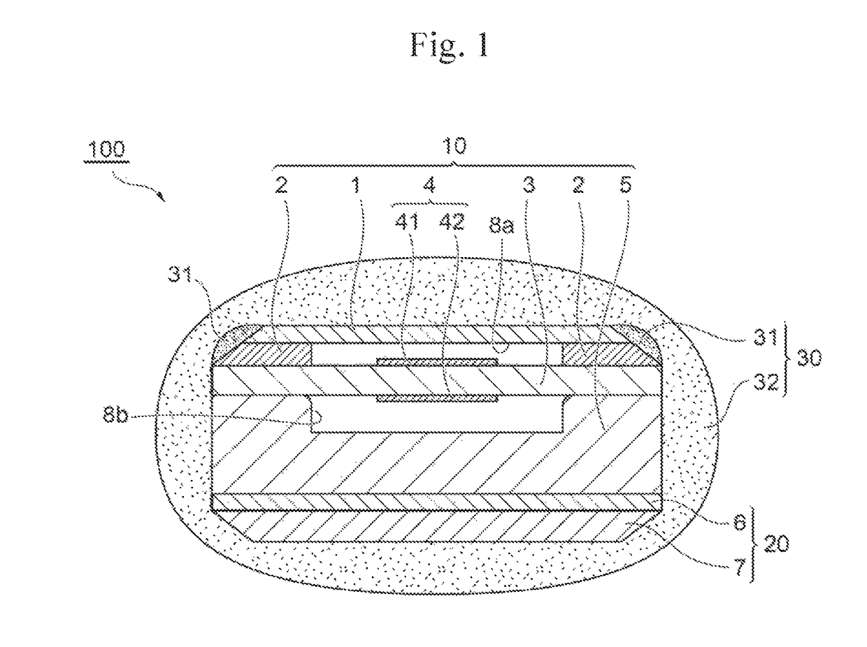
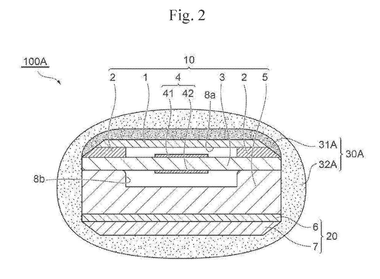
[0033]FIGS. 1 and 2 are schematic views each illustrating Embodiments 1 and 2 of the gas sensor element of the present invention.
[0034]First, a specific structure of the gas sensor element will be described with reference to FIG. 1. A gas sensor element 100 shown in FIG. 1 generally includes a detection portion 10 that detects the concentration of oxygen in the exhaust gas, a heat-generating portion 20 that is stacked on the detection portion 10, and a porous protective layer 30 that protects the periphery of the detection portion 10 and the heat-generating portion 20 against moisture in the exhaust gas and thus suppresses water-induced cracking of the detection portion 10 or the heat-generating portion 20 due to moisture that would otherwise reach the detection portion 10 or the heat-generating portion...
PUM
 Abstract
Description
Claims
Application Information
 - Generate Ideas
- Intellectual Property
- Life Sciences
- Materials
- Tech Scout
- Unparalleled Data Quality
- Higher Quality Content
- 60% Fewer Hallucinations
Browse by: Latest US Patents, China's latest patents, Technical Efficacy Thesaurus, Application Domain, Technology Topic, Popular Technical Reports.
© 2025 PatSnap. All rights reserved.Legal|Privacy policy|Modern Slavery Act Transparency Statement|Sitemap|About US| Contact US: help@patsnap.com