Method and system for exhaust particulate matter sensing

a technology of particulate matter and sensing method, which is applied in the direction of exhaust treatment electric control, machines/engines, instruments, etc., can solve the problems of not being able to reliably measure the quantity of pm passing through the dpf, the sensor may be prone to contamination, and the flow rate of exhaust gas entering the sensor may be reduced, so as to reduce the sensitivity of the pm sensor, the effect of increasing the exhaust flow

Inactive Publication Date: 2018-01-25
FORD GLOBAL TECH LLC
View PDF15 Cites 5 Cited by
  • Summary
  • Abstract
  • Description
  • Claims
  • Application Information

AI Technical Summary

Benefits of technology

[0005]However, the inventors herein have recognized potential issues with such systems. As one example, the amount of exhaust gas flowing into the PM sensor may be limited by the size, and shape of the perforations. In addition, since the exhaust gas has to undergo a complete reversal in flow direction to enter the PM sensor, the flow rate of exhaust gas entering the sensor may be reduced. This may, in turn, lead to reduced sensitivity of the PM sensor.
[0006]In one example, the issues described above may be addressed by a particulate matter (PM) assembly comprising a bent tube having a first closed end and a second outwardly flared end, a plurality of perforations formed proximate to the first end, and a sensor element positioned facing towards the plurality of perforations, the sensor element located upstream of the second end. In this way, the second end of the bent tube may form a venturi that serves to block larger particulates from entering the assembly, and additionally serves to increase exhaust flow into the sensor assembly. As a result, the sensitivity of the sensor may be increased.
[0007]As one example, an exhaust PM sensor assembly may be configured with sensor electrodes and may be positioned downstream of a particulate filter in an exhaust pipe. The PM sensor assembly may include a bent, protection tube that forms an L-shape. A first end of the bent tube may be closed, and coupled to the exhaust pipe. A sensor element may be positioned inside the assembly in front of a plurality of perforations; the sensor element, and the plurality of perforations are both located closer to the first end. A second end of the bent tube may be an open, outwardly flared end and may be located downstream of the first end (and the sensor element) and positioned within the exhaust pipe. The bent tube may have a uniform cross-section over the entire length, except at the second end. At the second end, the tube may include an outwardly angled portion that has increasing cross-section all the way to the tip of the bent tube, thus forming a venturi at the second end of the bent tube. As such, at the venturi, exhaust flows from the tip of the tube where the cross-section is higher, towards the first end of the bent tube with the smaller cross-section. As a result, the exhaust encounters a constriction within which the exhaust flow velocity is increased. The exhaust is then directed from the venturi that is located at the second end through the plurality of perforations towards the sensor element that is located proximate to the first end of the protection tube. Specifically, the exhaust is directed towards electrodes of the sensor element. When a controller applies a voltage across the electrodes of the sensor element, the particulates in the exhaust may be captured across the electrodes. Thus, an increased exhaust flow into the venturi may translate into an increased PM deposition across the electrodes of the sensor element. Thereby, the PM sensor may give an accurate measure of the exhaust particulates in the exhaust passage upstream of the particulate filter. In this way, the PM sensor may be used to diagnose leaks in the particulate filter in a reliable manner. When a soot load on the electrodes reaches a threshold soot load, the controller may apply a voltage to heat a heating element coupled to the sensor element to burn off the particulates deposited on the electrodes, thus regenerating the PM sensor.
[0008]In this way, by creating a venturi-like structure inside the PM sensor assembly, the exhaust flow inside the PM assembly may be increased, with a corresponding increase in sensor sensitivity. In addition, as the exhaust is streamed from the downstream side of the bent tube, the amount of larger particulates and / or water droplets impinging on the sensor element may be reduced. Specifically, due to their larger momentum, water droplets and / or larger particulates may flow past the venturi without redirecting their flow direction to enter the venturi. Therefore, the sensor element may be protected from impingement of water droplets and larger particulates. Overall, the functioning of the PM sensor assembly may be improved and PM sensor output may be more reliable.

Problems solved by technology

PM sensors may encounter issues with non-uniform deposition of soot on the sensor due to a bias in flow distribution across the surface of the sensor.
Further, PM sensors may be prone to contamination from an impingement of water droplets and / or larger particulates present in the exhaust gases.
If larger particulates adhere to electrodes of the sensor, the PM sensor may no longer be able to reliably measure the PM quantity passed through the DPF.
If the condensed water adheres to the electrodes of the sensor element, for example, the accuracy of the PM sensor may be compromised.
In addition, the condensed water adhering to the sensor element may cause the sensor element to get cracked due to thermal stress.
This can result in warranty issues.
Because of their larger momentum, the larger particulates and the water droplets may not be able to undergo a reversal in direction of flow and enter the PM sensor.
However, the inventors herein have recognized potential issues with such systems.
As one example, the amount of exhaust gas flowing into the PM sensor may be limited by the size, and shape of the perforations.
This may, in turn, lead to reduced sensitivity of the PM sensor.

Method used


Image

  • Method and system for exhaust particulate matter sensing
  • Method and system for exhaust particulate matter sensing
  • Method and system for exhaust particulate matter sensing

Examples


Embodiment Construction

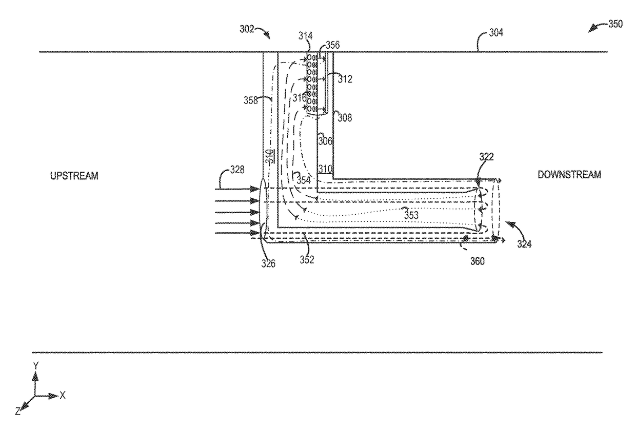
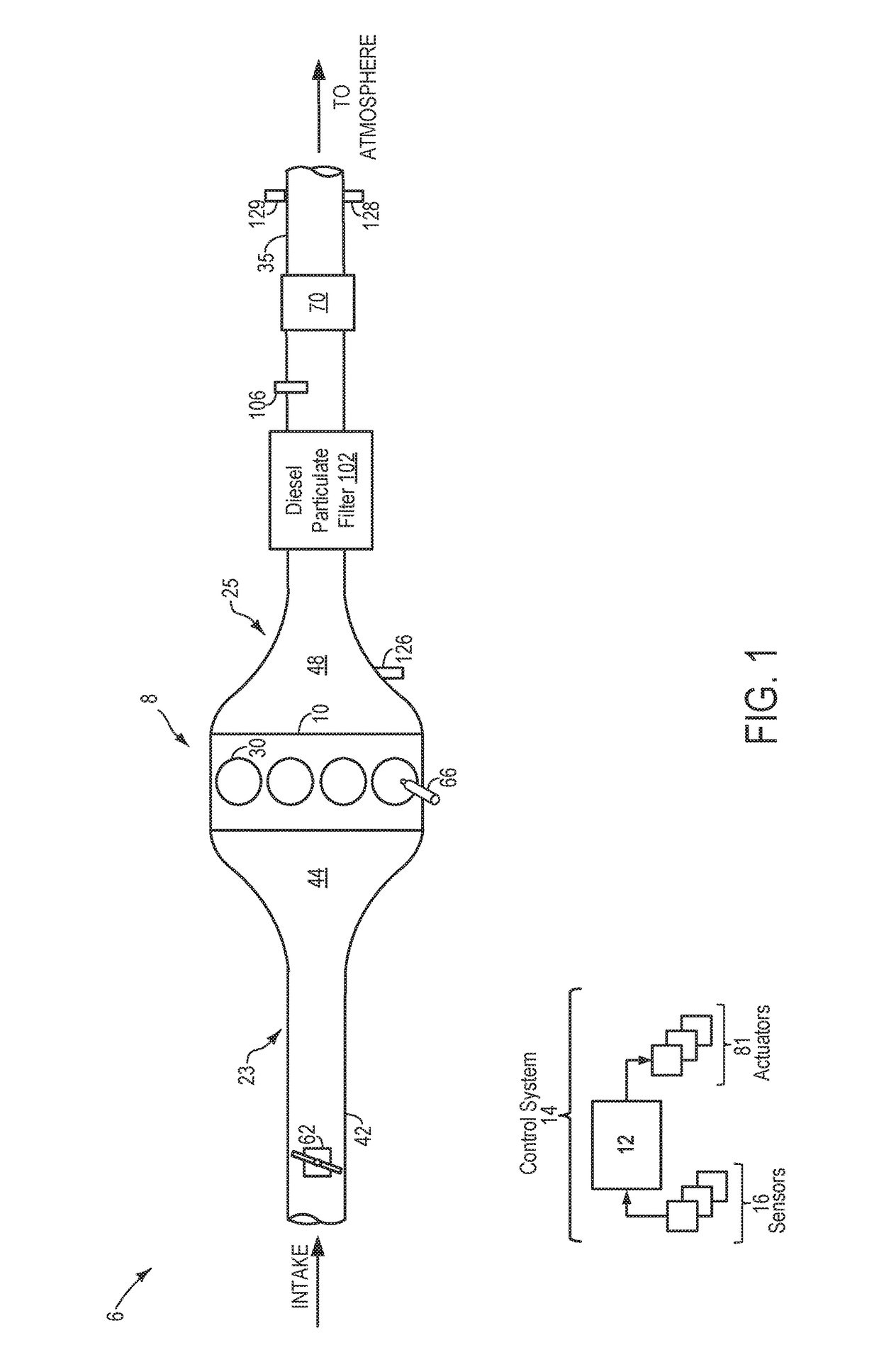
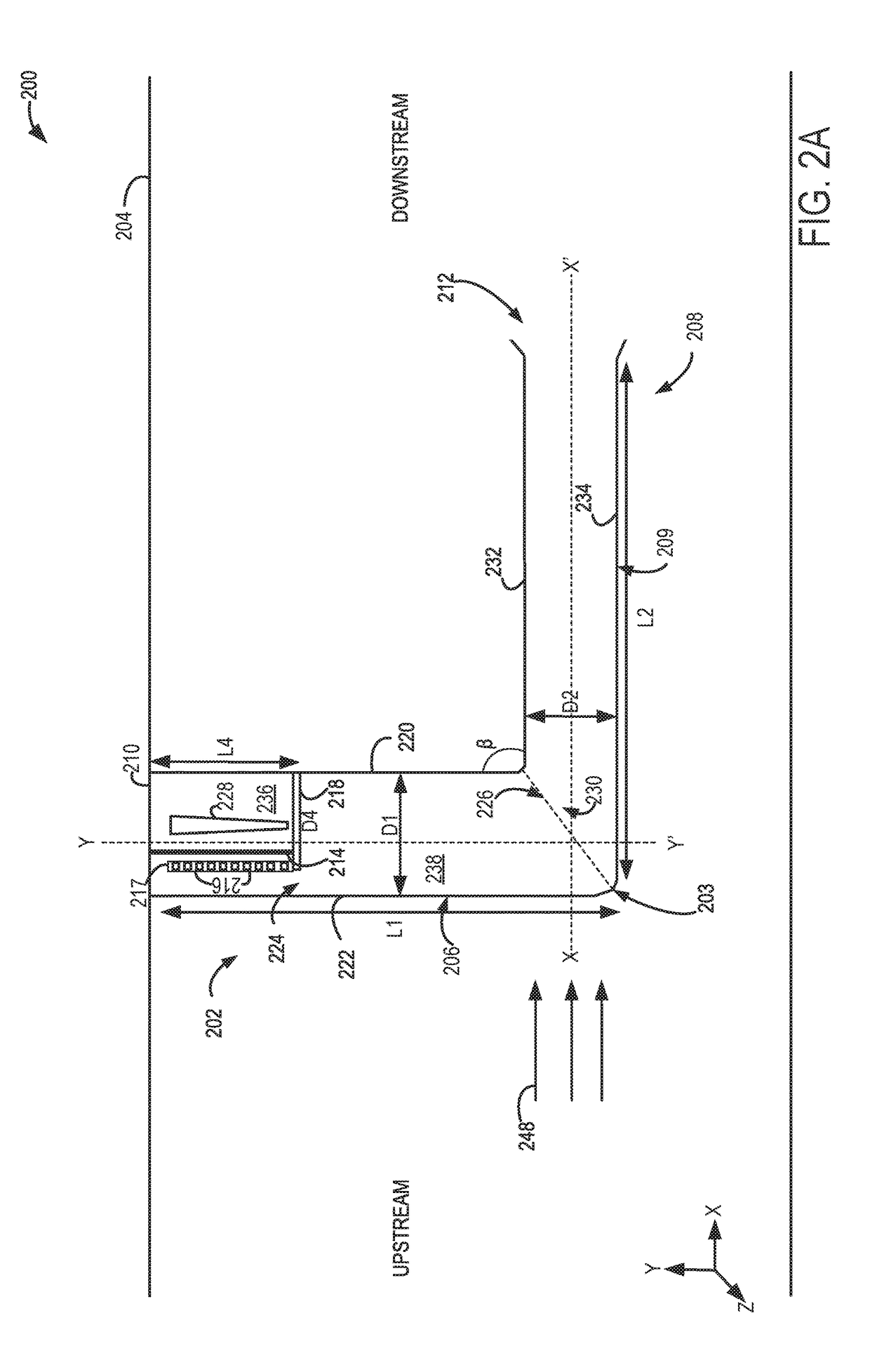
[0023]The following description relates to systems and methods for sensing particulate matter (PM) in an exhaust flow of an engine system, such as the engine system shown in FIG. 1. A first example PM sensor assembly shown in FIG. 2A may be coupled to an exhaust passage of the engine system. As such, the PM sensor assembly may include an L-shaped bent protection tube coupled to the exhaust passage via a first, closed end. In addition, the bent tube may include a second outwardly flared up (FIG. 2C) end placed within the exhaust passage. Herein, the second end may serve as an opening configured to direct exhaust from the exhaust passage into the PM sensor assembly (FIG. 2B). Specifically, the exhaust flows towards a sensor element through a plurality of perforations formed on a baffle. As such, the second end may include a venturi-like opening configured to increase exhaust flow at the opening of the PM sensor assembly. A second example PM sensor assembly may include the bent tube sh...


PUM

PropertyMeasurementUnit
angleaaaaaaaaaa
distanceaaaaaaaaaa
L-shapeaaaaaaaaaa

Abstract

Methods and systems are provided for a particulate matter (PM) sensor assembly positioned downstream of a diesel particulate filter in an exhaust system. In one example, a PM sensor assembly may include a bent tube having a first, upstream end coupled to an exhaust passage, and a second outwardly flared end at a downstream end of the assembly. In this way, the second end of the bent tube may form a venturi that serves to block larger particulates from entering the assembly, and additionally serves to increase exhaust flow into the sensor assembly.

Description

FIELD[0001]The present description relates generally to methods and systems for sensing particulate matter in an exhaust system.BACKGROUND / SUMMARY[0002]Engine emission control systems may utilize various exhaust sensors. One example sensor may be a particulate matter (PM) sensor, which indicates particulate matter mass and / or concentration in the exhaust gas. In one example, the PM sensor may operate by accumulating particulate matter over time and providing an indication of the degree of accumulation as a measure of exhaust particulate matter levels. The PM sensor may be located upstream and / or downstream of a diesel particulate filter, and may be used to sense particulate matter loading on the particulate filter and diagnose operation of the particulate filter.[0003]PM sensors may encounter issues with non-uniform deposition of soot on the sensor due to a bias in flow distribution across the surface of the sensor. Further, PM sensors may be prone to contamination from an impingeme...

Claims


Application Information

Patent Timeline
Patent Type & Authority Applications(United States)
IPC IPC(8): F01N11/00F01N3/033G01N15/06
CPCF01N11/00F01N3/033G01N15/0656G01N2015/0046F01N3/021G01N15/0606F01N2560/05F01N2900/0416Y02T10/12Y02T10/40G01N1/38F02B3/06G01N1/2205G01N1/24
Inventor ZHANG, XIAOGANG
Owner FORD GLOBAL TECH LLC
Why Eureka
Try Eureka