LED light source with diffuser

a technology of led light source and diffuser, which is applied in the direction of basic electric elements, electrical equipment, and semiconductor devices, etc., can solve the problems of high glare, high cost, and high cost of leds, and achieves low cost, high efficacy, and uniform radiance distribution.

Inactive Publication Date: 2018-01-25
OSRAM SYLVANIA INC
View PDF4 Cites 9 Cited by
  • Summary
  • Abstract
  • Description
  • Claims
  • Application Information

AI Technical Summary

Benefits of technology

[0005]It is another object of the invention to provide a light source that homogenizes the light produced by a large area array of forward directed LEDs mounted on either a flexible or rigid substrate, while achieving a low-profile form factor and maintaining high efficacy.
[0006]

Problems solved by technology

However, by their nature, LEDs are nearly point sources that have high-glare if not properly lensed or diffused.
In particular, large area light sources based on arrays of LEDs to replace common fluorescent fixtures or other low radiance area light sources often require complex and expensive components to convert the high-radiance LED emission into low glare, large area surface emission.
Often, this is done using an edge-lit approach to have a low-profile form factor, but such solutions require expensive

Method used


Image

  • LED light source with diffuser
  • LED light source with diffuser
  • LED light source with diffuser

Examples


example 1

yer Diffuser

[0056]In this Example, glare reduction is demonstrated using a single layer configuration. The layers in FIG. 1 are combined into a single homogeneous scattering layer. The host is silicone, preferably a methyl silicone, because of its lower optical absorption. Typical methyl silicone losses are on the order of 0.01 dB / cm at 633 nm and 0.03 dB / cm at 400 nm. This puts a worst case limit on the host absorption coefficient α−1, which would be used in Equation (10). For scattering centers, sub-micron titanium dioxide (TiO2) particles in the rutile form are excellent scattering centers because of their very high refractive index (˜2.6) and very high transparency in the visible.

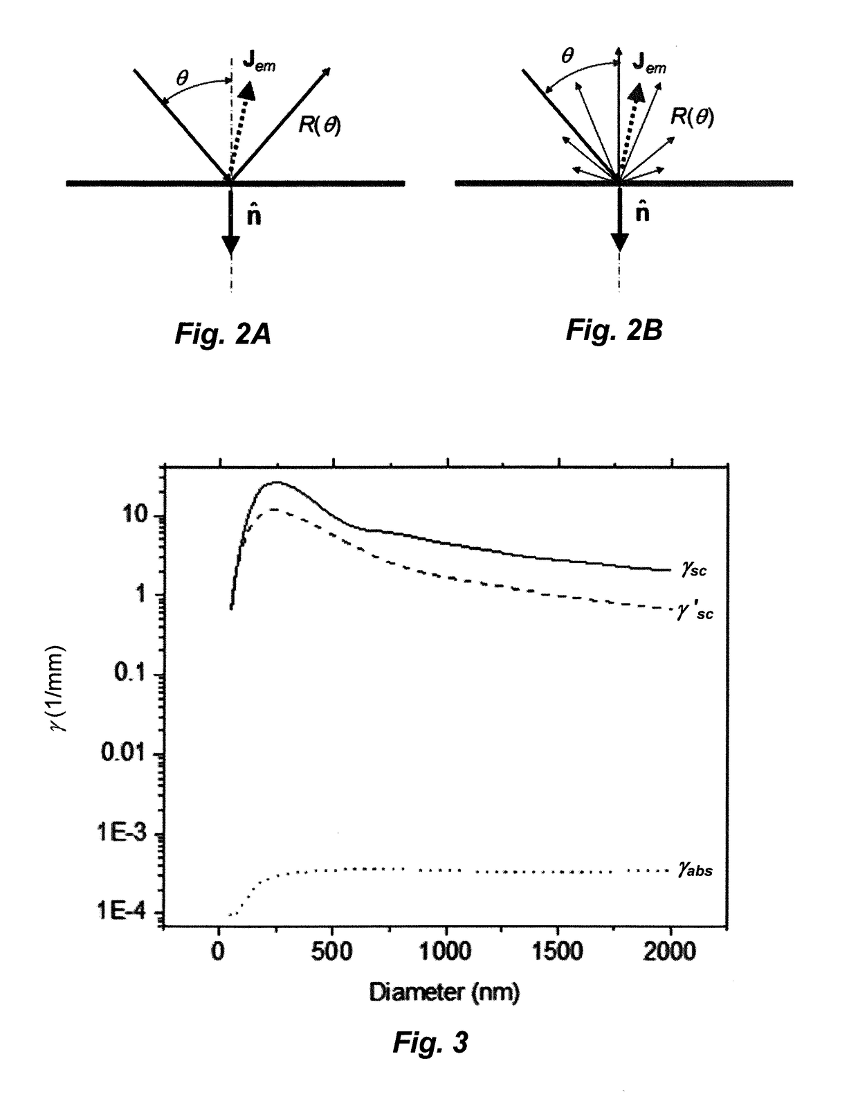
[0057]Taking the index of refraction for a typical methyl silicone of 1.43, FIGS. 3 and 4 show plots of various scattering coefficients for TiO2 particles embedded in silicone. FIG. 3 shows the variation of the scattering coefficients γ′sc, γ′sc, and γabs versus mean diameter for a fixed mass loading RM...

example 2

Diffuser

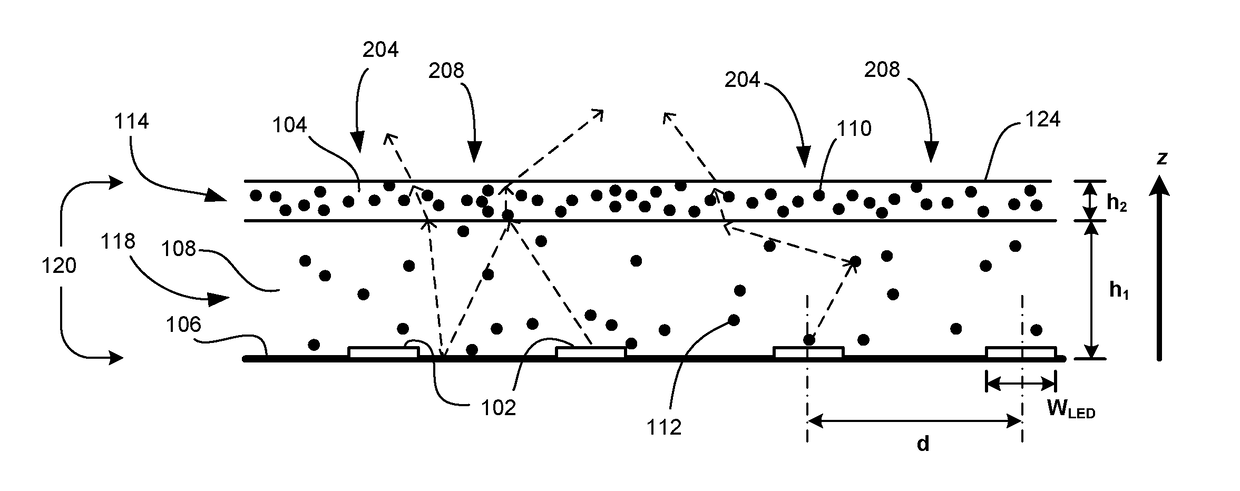
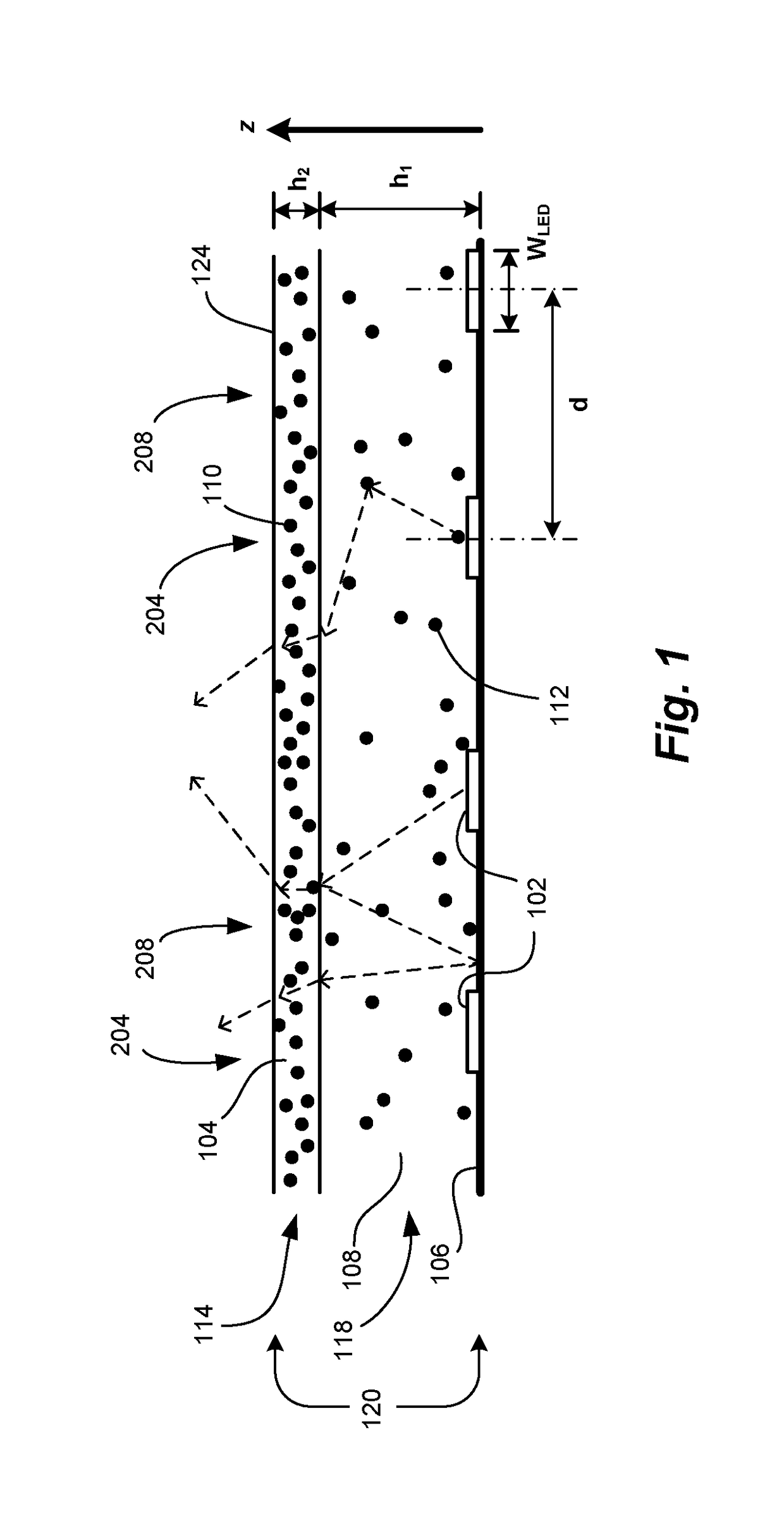
[0061]In the second Example, a homogeneous two-layer approach (FIG. 1) in accordance with a preferred embodiment of this invention is used to further reduce glare and increase near-field uniformity. Simulations were made for a similarly thick stack: h1=4.5 mm and h2=0.5 mm. In this simulation, the LED thickness was reduced; LEDs (with phosphor) were assumed to be 1 mm×1 mm×0.5 mm. The LED reflectance was also reduced slightly to RLED=0.87 to better match high-quality dies. Table 1 shows the parameter range used; only the scattering coefficient of the lower diffusing layer 118 was changed. The corresponding TiO2 loadings ranged from 0.0043%-0.22%. For the upper diffusing layer 114 the corresponding TiO2 loading was approximately 0.22%.

[0062]Results show that when the lower diffusing layer 118 is low scattering, efficiencies and uniformity are very good and far better than the single layer approach as shown in FIG. 7 and Table 1. The lowest scattering coefficient for the lower...

example 3

Diffuser

[0064]One of the disadvantages of the two-layer configuration is the need for a thicker layer of scattering media. This can lead to excess weight, manufacturing time, higher probability of defects, and expense. To achieve a thinner layer with comparable glare reduction, uniformity, and efficiency, one can employ lateral variations (x-y plane orthogonal to the z axis) in the upper diffusing layer to reduce transmission of light above the LED region (FIG. 1, region 204) while having increased transmission of light away from the LED (FIG. 1, region 208).

[0065]A suitable scattering distribution in the upper diffusing layer to accomplish this is a two-dimensional (2D) radial Gaussian profile for the reduced scattering coefficient in the upper layer. We use the following form for simulations over the x-y plane:

γ′sc-2(x,y)=γ′0+(γmax−γ′0)e−(x2+y2) / 2σ2  (20)

Here, the distribution is determined by minimum and maximum reduced scattering coefficient values, γ′0 and γ′max, and a standard...


PUM


Abstract

There is herein described a light source that homogenizes the light produced by a large area array of forward directed LEDs mounted on highly reflective substrate, while achieving a low-profile form factor and maintaining high efficacy. The LED light source employs a diffuser comprised of two diffusing layers: a low scattering diffusing layer bonded to the LEDs and a high scattering diffusing layer that is bonded to the low scattering diffusing layer. The LED light source achieves good diffuse illumination with a thin diffuser by making use of a light channeling effect between the highly reflective substrate and the high backscattering from the high scattering diffusing layer.

Description

CROSS REFERENCES TO RELATED APPLICATIONS[0001]The present application is an international application that claims the benefit of U.S. Provisional Application No. 62 / 118,302 filed Feb. 19, 2015, which is herein incorporated by reference.BACKGROUND OF THE INVENTION[0002]Solid-state light sources based on light-emitting diodes (LEDs) offer great potential for high-efficacy lighting with excellent color rendition. However, by their nature, LEDs are nearly point sources that have high-glare if not properly lensed or diffused. In particular, large area light sources based on arrays of LEDs to replace common fluorescent fixtures or other low radiance area light sources often require complex and expensive components to convert the high-radiance LED emission into low glare, large area surface emission. Often, this is done using an edge-lit approach to have a low-profile form factor, but such solutions require expensive higher power LEDs and therefore additional heat-sinking. More detrimental...

Claims


Application Information

Patent Timeline
IPC IPC(8): H01L33/60H01L33/56H01L25/075
CPCH01L33/60H01L25/0753H01L33/56H01L2933/0091
Inventor LENEF, ALANHAMBY, DAVIDAVALLON, JAMES
Owner OSRAM SYLVANIA INC
Why Eureka
Try Eureka