Method for controlling magnetic catheter by using magnetic-field-generated magnetic annulus

a magnetic annulus and magnetic catheter technology, applied in the field of magnetic catheter control, can solve the problems of reducing the control effect, reducing the efficiency of the control device, and requiring high magnetic flux density, so as to facilitate the bending motion, and high magnetic flux density

Inactive Publication Date: 2018-02-01
NAT CHENG KUNG UNIV
View PDF0 Cites 6 Cited by
  • Summary
  • Abstract
  • Description
  • Claims
  • Application Information

AI Technical Summary

Benefits of technology

[0022]1. By applying an acting force on the magnetic member via an annular region (magnetic annulus) that has a relative high magnetic flux density in a magnetic field, it is easier for the magnetic member to drive the flexible section to perform a bending motion.
[0023]2. When the magnetic member enters a magnetic annulus of a resultant magnetic field generated by repulsion existing between like poles of two magnets, thrust is exerted on a head portion of the magnetic member to facilitate the bending motion and increase the bending angle of the flexible section. Thus, when the resultant magnetic field is generated by electromagnets, the required power output of the electromagnets can be reduced.

Problems solved by technology

However, using plural electromagnets renders the prior-art device bulky and expensive.
As a result, once the catheter to be controlled enters an area where the magnetic flux density is low, the controlling effect is degraded.
Second, when the bending of the catheter is purely depending on the attraction generated in the magnetic field, high magnetic flux density is required.
For providing such high magnetic flux density, the electromagnets need to be supplied with extremely high current, and this is often costly.
Third, the attraction generated in the magnetic field can only make the catheter between the two opposite magnets bend toward one of the magnets at a relatively limited bending angle.

Method used


Image

  • Method for controlling magnetic catheter by using magnetic-field-generated magnetic annulus
  • Method for controlling magnetic catheter by using magnetic-field-generated magnetic annulus
  • Method for controlling magnetic catheter by using magnetic-field-generated magnetic annulus

Examples


Embodiment Construction

[0054]For further illustrating the means and functions on which the present invention achieves the certain objectives, the following description, in conjunction with the accompanying drawings and preferred embodiments, is set forth as below to illustrate the implement, structure, features and effects of the subject matter of the present invention.

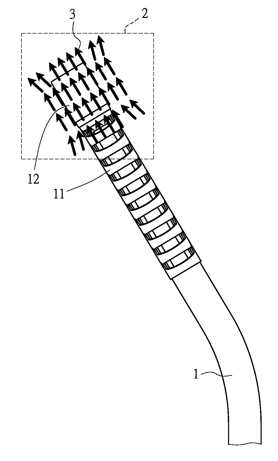
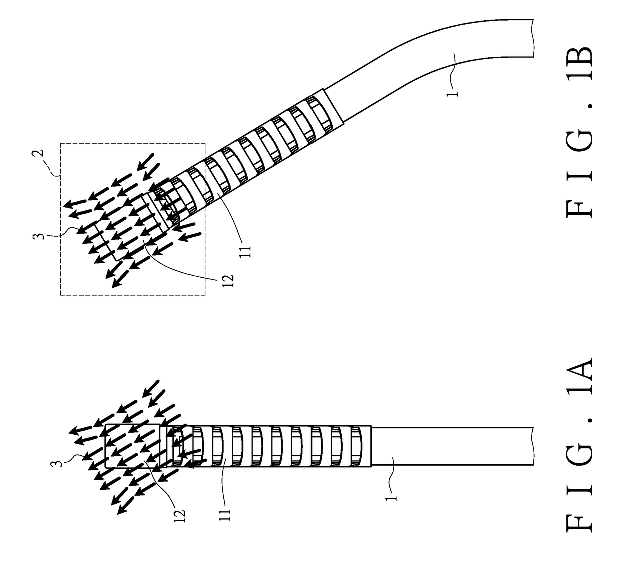
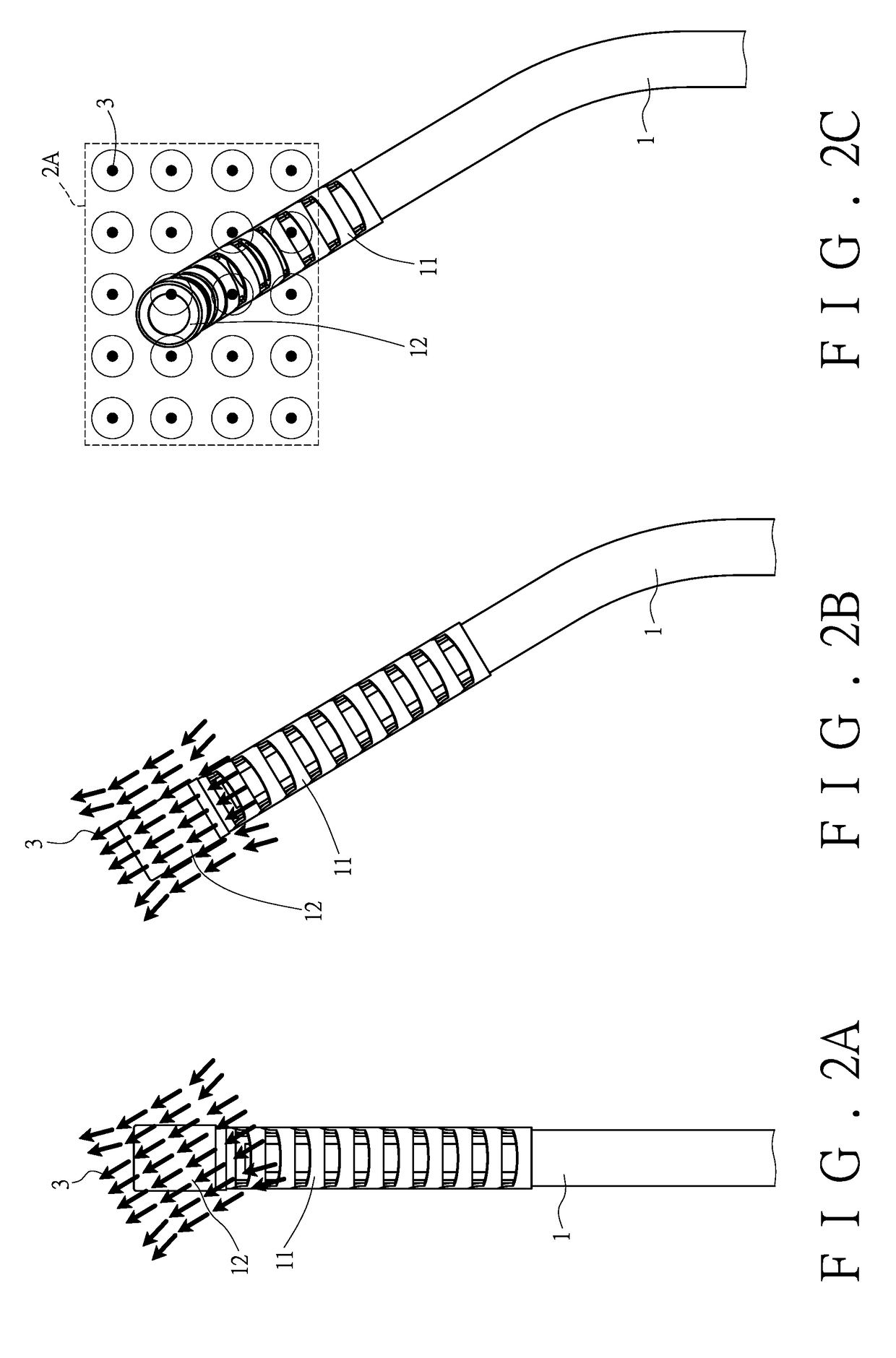
[0055]Referring to FIG. 1A, in the present embodiment, a magnetic catheter (1) has a front section formed as a flexible section. According to the present embodiment, the flexible section is a multi joint section (11) with each joint thereof having a single bending degree of freedom. At a free end of the multi joint section (11), a magnetic member (12) is provided. The magnetic member (12) is an axial magnet. Therein, the magnetic catheter (1) is capable of performing a feeding motion and a rotating motion along a linear first route. The first route is an extending route of the magnetic catheter (1).

[0056]In embodiments of the present invent...


PUM


Abstract

A method for controlling a magnetic catheter by using a magnetic-field-generated magnetic annulus is disclosed. The magnetic catheter has a free end provided with a magnetic member. A resultant magnetic field between at least two magnets generates a magnetic annulus. The magnetic catheter is placed into the magnetic annulus, so that the magnetic member is affected by the magnetic force from the magnetic annulus to guide the magnetic catheter to perform a preset motion. The magnetic catheter has a flexible front section, so that the flexible section can perform a bending motion when led by the magnetic member. The resultant magnetic field is generated by arranging the two magnets with their like poles facing each other, so that the magnetic member is thrust when entering the magnetic annulus. This facilitates the bending motion of the flexible section.

Description

BACKGROUND OF THE INVENTION1. Technical Field[0001]The present invention relates to a method for controlling a magnetic catheter, and more particularly to a method of moving a magnetic catheter by applying an acting force thereon via an annular region, hereafter called magnetic annulus, which has a relative high magnetic flux density in a magnetic field and offsets from a center of the magnetic field.2. Description of Related Art[0002]Thanks to the development of modern medical technology, many physical issues used to rely only on conventional open surgery can now be well treated and controlled using interventional catheter or endoscopic technology. This change helps to free patients from the discomfort caused by surgical operation, and minimize the risk of surgical infection.[0003]To well control a flexible catheter, magnetic control has become an increasingly interesting scientific field. For example, U.S. Pat. No. 6,311,082 titled “DIGITAL MAGNETIC SYSTEM FOR MAGNETIC SURGERY” di...

Claims


Application Information

Patent Timeline
Patent Type & Authority Applications(United States)
IPC IPC(8): A61M25/01A61B1/00A61B17/00A61B34/00
CPCA61M25/0127A61B34/73A61B1/00133A61B2017/00318A61B17/00234A61B2034/732A61B2017/00314A61B1/00158A61B2017/00411A61B2017/00876A61M25/0138A61M25/0158
Inventor LUO, CHING-HSINGSHIEH, MENG-DARCHANG, CHIEN-CHENTSAI, MING-HUNGFANG, HSIN-ENZHANG, YILIN, YANG-BENYANG, WEN-HORNGSHIH, MING-CHANGTAI, CHENG-CHI
Owner NAT CHENG KUNG UNIV
Why Eureka
Try Eureka