Apparatuses and methods for laser processing

a technology of laser processing and apparatus, applied in glass making apparatus, manufacturing tools, welding/soldering/cutting articles, etc., can solve the problems of laser beam focal line causing a line defect within the transparent workpiece, and the contour line may comprise workpiece defects

Active Publication Date: 2018-02-01
CORNING INC
View PDF2 Cites 22 Cited by
  • Summary
  • Abstract
  • Description
  • Claims
  • Application Information

AI Technical Summary

Problems solved by technology

The contour line may comprise defects in the workpiece.
The pulsed laser beam focal line may produce a line defect within the transparent workpiece.

Method used


Image

  • Apparatuses and methods for laser processing
  • Apparatuses and methods for laser processing
  • Apparatuses and methods for laser processing

Examples


Embodiment Construction

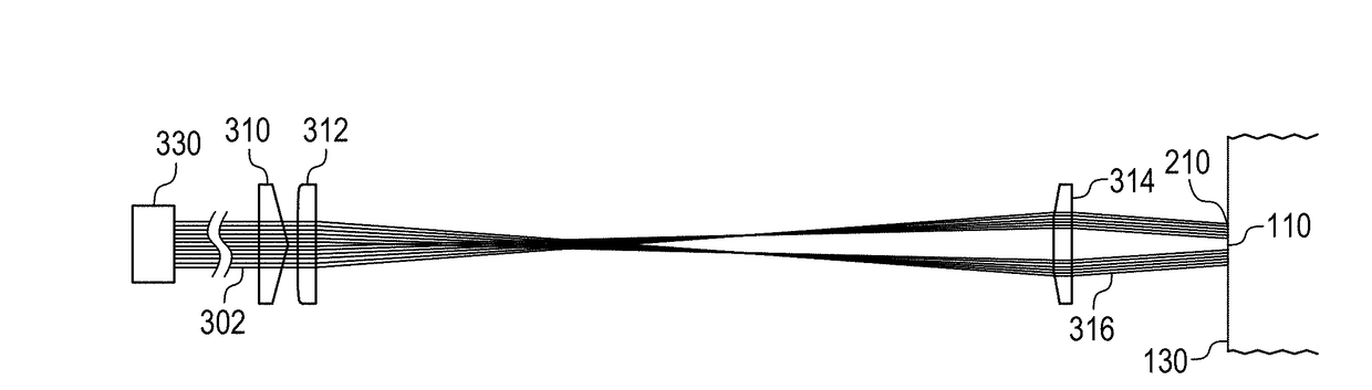
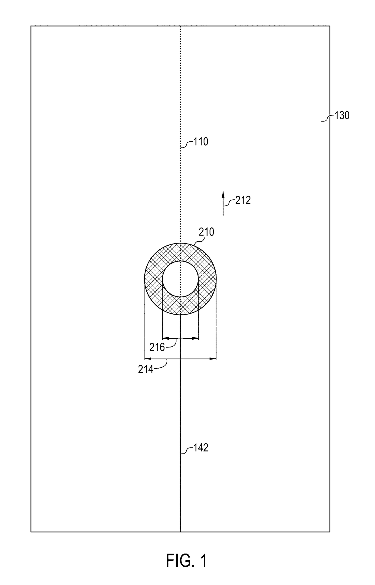
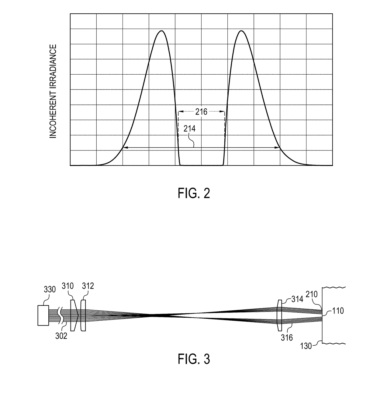
[0031]Reference will now be made in detail to embodiments of processes for laser processing transparent workpieces, such as glass workpieces, examples of which are illustrated in the accompanying drawings. Whenever possible, the same reference numerals will be used throughout the drawings to refer to the same or like parts. According to one or more embodiments described herein, a transparent workpiece may be laser processed to separate the transparent workpiece into two or more portions. Generally, the process involves at least a first step of forming a contour line comprising defects in the transparent workpiece, and a second step of separating the transparent workpiece along the contour line by subjecting the transparent workpiece to an infrared laser beam at or near the contour line. According to one embodiment, a pulsed laser beam may be utilized to create a series of line defects in the transparent workpiece thereby defining the contour line. These line defects may be referred ...


PUM

PropertyMeasurementUnit
outer diameteraaaaaaaaaa
speedaaaaaaaaaa
poweraaaaaaaaaa

Abstract

A workpiece may be laser processed by a method that may include forming a contour line in the workpiece, and directing an infrared laser beam onto the workpiece along or near the contour line to separate the workpiece along the contour line. The contour line may include defects in the workpiece. The infrared laser beam may have a beam profile such that a greater distribution of cumulated energy from the infrared laser beam is located in areas adjacent to the contour line than directly on the contour line.

Description

[0001]This application claims the benefit of priority under 35 U.S.C. §119 of U.S. Provisional Application Ser. No. 62 / 368,571 filed on Jul. 29, 2016 the content of which is relied upon and incorporated herein by reference in its entirety.BACKGROUNDField[0002]The present specification generally relates to apparatuses and methods for laser processing workpieces.Technical Background[0003]The area of laser processing of materials encompasses a wide variety of applications that involve cutting, drilling, milling, welding, melting, etc. of different types of materials. Among these processes, one that is of particular interest is cutting or separating different types of transparent substrates in a process that may be utilized in the production of materials such as glass, sapphire, or fused silica for thin film transistors (TFT) or display materials for electronic devices.[0004]From process development and cost perspectives there are many opportunities for improvement in cutting and separa...

Claims


Application Information

Patent Timeline
Patent Type & Authority Applications(United States)
IPC IPC(8): C03B33/02B23K26/00B23K26/53B23K26/073
CPCC03B33/0222B23K26/0734B23K2203/54B23K26/0006B23K26/53B23K26/0057B23K26/08C03B33/091B23K26/0624B23K2101/40B23K2103/54B23K26/0738
Inventor SCHNITZLER, DANIELSCHILLINGER, HELMUT
Owner CORNING INC
Why Eureka
Try Eureka