Flow control actuator for reciprocating compressors

Active Publication Date: 2018-02-01
DOTT ING MARIO COZZANI
View PDF3 Cites 1 Cited by
  • Summary
  • Abstract
  • Description
  • Claims
  • Application Information

AI Technical Summary

Benefits of technology

The invention provides an actuator that can control the delivery rate of reciprocating compressors by acting on the suction valve on each compression cycle. The actuator is safer, balanced, reliable, and applicable to traditional automatic suction valves of reciprocating compressors. It also has advantages from the pressure compensation viewpoint and is effective in limiting friction between the various parts in movement.

Problems solved by technology

One of the major issues to solve in these devices is to prevent compressed gas from some way coming into contact with the windings of the electromagnets or with the associated electronic devices, such as the position sensor of the moving element for example; in fact, a mixture composed, for example, of oxygen present in the air and an flammable gas, can explode if exposed to an ignition source of electrical origin.
Since the actuator's rod slides inside an associated seat where the annular sealing elements are located, one of the biggest problems with this type of actuator is the wear on these sealing elements, and hence the risk that compressed gas enters the chambers housing the armature and so makes contact with the windings of the actuator's electromagnets.
To reduce the risk of compressed gas returning to these chambers, precisely in the event of wear on the rod's seals, it is known to use systems of recovering gas through the rod and to use nitrogen barriers or barriers of equivalent inert gases that reduce the likelihood, but which are not found to be entirely efficient.
These sealing elements along which the actuator's rod slides can also be damaged by possible impurities or metallic particles that might be present in the compressed gas.
Furthermore, unlike pneumatic or hydraulic actuators, a gas leak in electromechanical actuators from the rod of the actuator, following possible damage to the dynamic sealing elements of the rod, implies high safety risks for the entire compressor, as, in cases of easily flammable gases such as, for example, hydrogen, ethylene and, more generally, the various hydrocarbons, the gas would enter the chambers housing the electromagnets.
As is known, to prevent possible infiltrations of compressed gas affecting the windings of the electromagnets, resin finishing processes are applied to them, but this resin finish is not sufficient to ensure there are no infiltrations of the compressed gas.
It should also be considered that the possible formation of air pockets inside or beneath the resin finish and gas infiltrations jeopardise not only the actuator, but the compressor itself.

Method used


Image

  • Flow control actuator for reciprocating compressors
  • Flow control actuator for reciprocating compressors
  • Flow control actuator for reciprocating compressors

Examples


Embodiment Construction

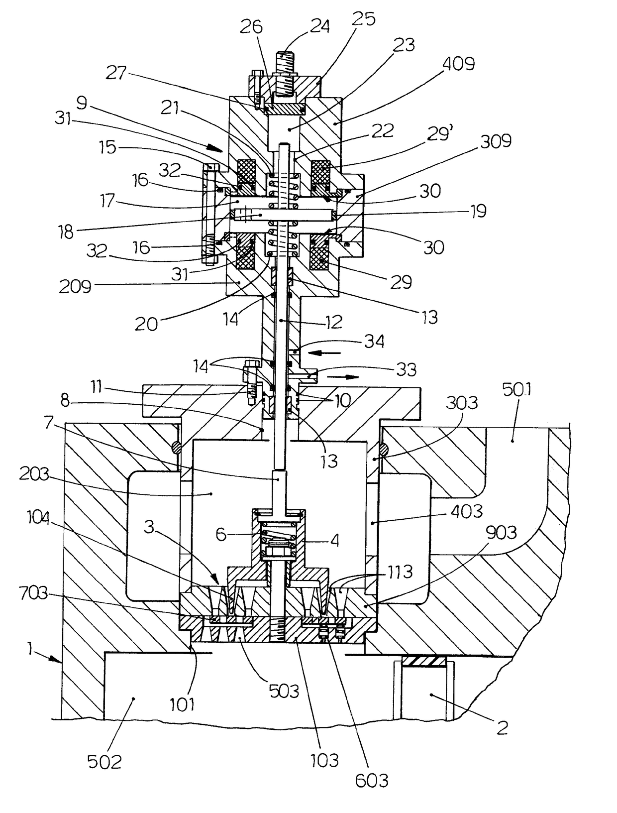
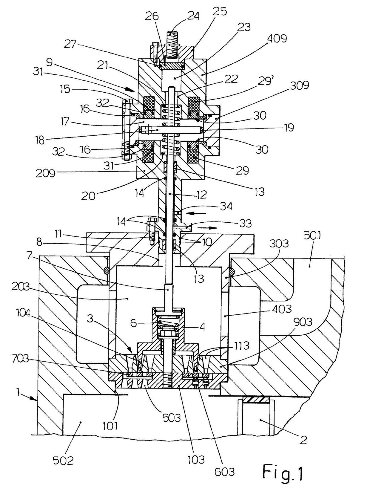
[0039]With reference to the accompanying drawings and with particular reference to FIGS. 1 and 2 thereof, reference numeral 1 indicates the cylinder of a (partially shown) reciprocating compressor, a cylinder that can be a single or double acting and within which a piston 2 slides. There is an opening 101 on a wall of the cylinder for housing the suction valve 3. The suction chamber 203 places the suction line 501 in communication with the chamber 502, in which compression of the fluid takes place. The valve 3 is locked in the cylinder 1 by means of the covers 303. The suction valve 3 is mainly composed of the following components: a seat 903, provided with ducts 113 for passage of the gas, a counter-seat 103, this also provided with ducts 503 for passage of the gas, elastic loading means 603, at least one sealing element 703, and a pusher 4, sliding axially with respect to the opening 101, with the purpose of acting on the obturator 703 through the legs 104 to force the valve 3 int...


PUM


Abstract

An electromechanical actuator for controlling the delivery rate of reciprocating compressors, comprising: a movable rod designed to cooperate at one end with a suction valve of a reciprocating compressor and at the other with a moving element made of a magnetizable material; at least one chamber in which said moving element is housed and onto which at least one winding of an electromagnet positioned inside a seat facing said chamber protrudes, there being positioned between said winding and said chamber at least one protective element made of a non-magnetic material and provided with static sealing elements and designed to keep the winding of the electromagnet separated from the chamber in which said moving element is housed, characterized in that said protective element made of a non-magnetic material comprises at least two series of static sealing elements, a first series being positioned internally to the protective element and a second series being positioned externally to the protective element, with gas recovery holes being provided between said series of static sealing elements, and in that at least one hole for connection to a gas bleeding and washing circuit is provided in said chamber.

Description

CROSS-REFERENCE TO RELATED APPLICATIONS[0001]The present application claims priority to PCT International Application No. PCT / IB2016 / 050706 filed on Feb. 10, 2016, which application claims priority to Italian Patent Application No. GE2015A000016 filed Feb. 11, 2015, the entirety of the disclosures of which are expressly incorporated herein by reference.STATEMENT RE: FEDERALLY SPONSORED RESEARCH / DEVELOPMENT[0002]Not Applicable.BACKGROUND[0003]The present invention relates to reciprocating compressors, in particular to an actuator for controlling the delivery rate of reciprocating compressors and, more specifically, an electromechanical actuator for the continuous return flow control of the suction valve(s) of reciprocating compressors, i.e. an electromechanical actuator capable of controlling the suction valve on each compression cycle.[0004]Return flow control is one of the known systems of flow control in reciprocating compressors and is implemented by delaying the closure of the s...

Claims


Application Information

Patent Timeline
IPC IPC(8): F16K31/06F04B39/10F04B39/08
CPCF16K31/0679F04B39/08F04B39/10F04B49/243F04B53/10H01F7/1638H01F2007/1692
Inventor SCHIAVONE, MASSIMORAGGI, ANDREA
Owner DOTT ING MARIO COZZANI
Why Eureka
Try Eureka