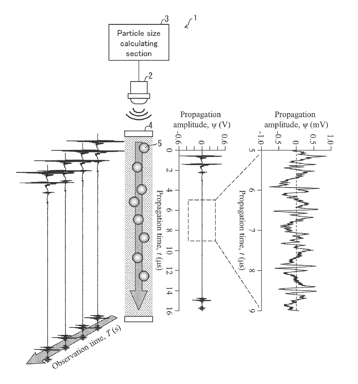
Ultrasonic particle size measurement device and ultrasonic measurement device
a measurement device and ultrasonic technology, applied in measurement devices, particle and sedimentation analysis, instruments, etc., can solve the problems of difficult light transmission, difficult to carry out measurement with respect to turbid samples, etc., and achieve favorable sn ratio, high accuracy, and rapid motion
- Summary
- Abstract
- Description
- Claims
- Application Information
AI Technical Summary
Benefits of technology
Problems solved by technology
Method used
Image

Examples
embodiment 1
[0062](Overview of Embodiment 1)
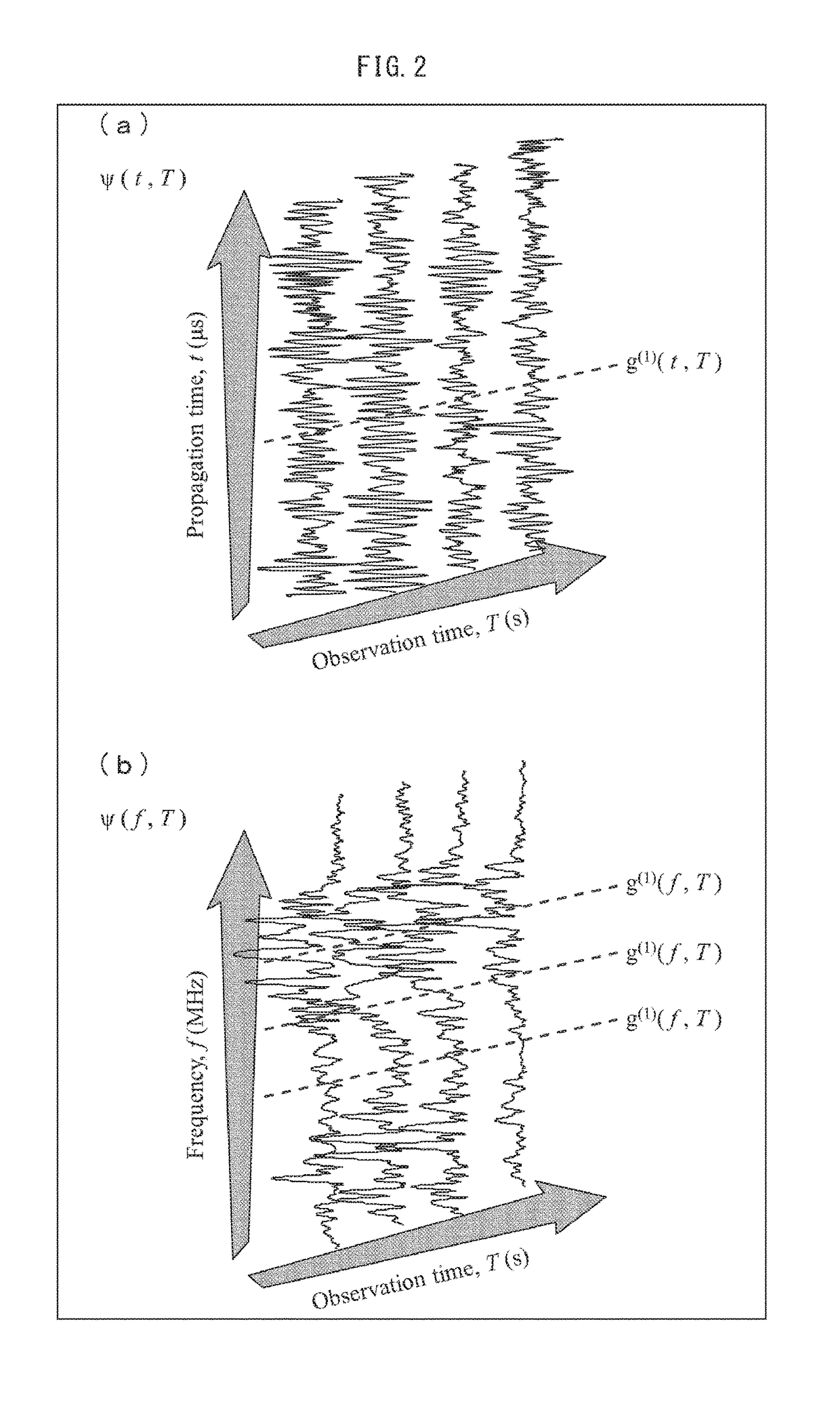
[0063]The reason why a measurement error of approximately 10% occurs in a particle size measured by the conventional dynamic ultrasound scattering method (Non-patent Literature 5) is largely due to the fact that emitted light is a laser having a narrow wavelength distribution, whereas an ultrasonic pulse is a “broadband” pulse having a broad wavelength distribution and constituted by an emitted wave containing various frequency components. An ultrasonic pulse that allows various broad frequency bands to be covered by measurement carried out one time is convenient in a spectroscopy experiment in which frequency analysis is carried out. Such a distribution of various frequency components inhibits precise determination of a location of a particle at a given instantaneous time and a particle size. According to Embodiment 1, an ultrasonic pulse obtained along a time axis is subjected to a Fourier transform and analyzed in a frequency space. It has been con...
embodiment 2
[0119](Overview of Embodiment 2)
[0120]Embodiment 2 allows particle size measurement to be carried out at a higher S / N ratio and in a shorter time in a case where a particle moves at an extremely low velocity. Embodiment 2 proposes a method in which great ultrasonic energy is intentionally externally applied to fine particles (dispersoids) dispersed into a liquid (dispersion medium) and a particle size of the fine particles is calculated from a velocity (ultrasonic fine particle velocity) induced in the fine particles by the application of the ultrasonic energy. Note that the conventional dynamic ultrasound scattering method in which a particle size is found in accordance with a sedimentation velocity is a simple and easy particle size measuring method with respect to a fine particle. Note, however, that according to the conventional dynamic ultrasound scattering method, it is necessary to start measurement after waiting for a fine particle to reach a state of steady motion. Thus, a ...
PUM
| Property | Measurement | Unit |
|---|---|---|
| particle size | aaaaa | aaaaa |
| particle size | aaaaa | aaaaa |
| frequency | aaaaa | aaaaa |
Abstract
Description
Claims
Application Information