Method and apparatus for remotely determining antenna input impedance

a technology of remote sensing and antenna input, which is applied in the direction of antenna radiation diagram, transmission monitoring, receiver monitoring, etc., can solve the problems of antenna loss of efficiency, affecting antenna impedance, and varying from its design parameters

Active Publication Date: 2018-02-01
JUE MARTIN F
View PDF3 Cites 1 Cited by
  • Summary
  • Abstract
  • Description
  • Claims
  • Application Information

AI Technical Summary

Benefits of technology

[0024]Having described an automatic antenna tuner characterized by an LC circuit, the result is that by simply viewing a display on the automatic antenna tuner one can read out the actual instantaneous antenna input impedance without having to physically go up to the antenna. With the automatic antenna tuner, not only is the antenna tuned in a traditional sense, an

Problems solved by technology

It has long been a problem to measure antenna impedance at the feed point of an antenna when the antenna has been installed or is in place and is remote from the transmitter to which is coupled.
While this couples maximum power from the transmitter to the transmitter end of the transmission line, it does not address any mismatch between transmitter output impedance and antenna input impedance.
In operation of the radio station, whether it is a commercial radio station or amateur radio station, oftentimes environmental factors affect the antenna impedance.
For instance, snow, rain, wind and moisture can affect the antenna input impedance which causes it to vary from its design parameters.
Also corrosion and wear can alter the input impedance of the antenna such that the antenna loses its efficiency.
However this loss of efficiency is not detectable at the transmitter, which is typically remote from the antenna, and is coupled to the antenna by a length of transmission line.
Thus technicians at the transmitter have no way of knowing the actual condition of the antenna and cannot, for instance, be made aware of changes in the antenna input impedance.
The resu

Method used


Image

  • Method and apparatus for remotely determining antenna input impedance
  • Method and apparatus for remotely determining antenna input impedance
  • Method and apparatus for remotely determining antenna input impedance

Examples


Embodiment Construction

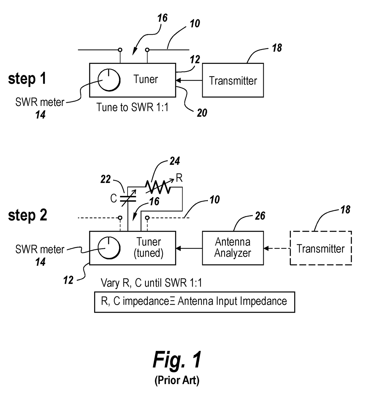
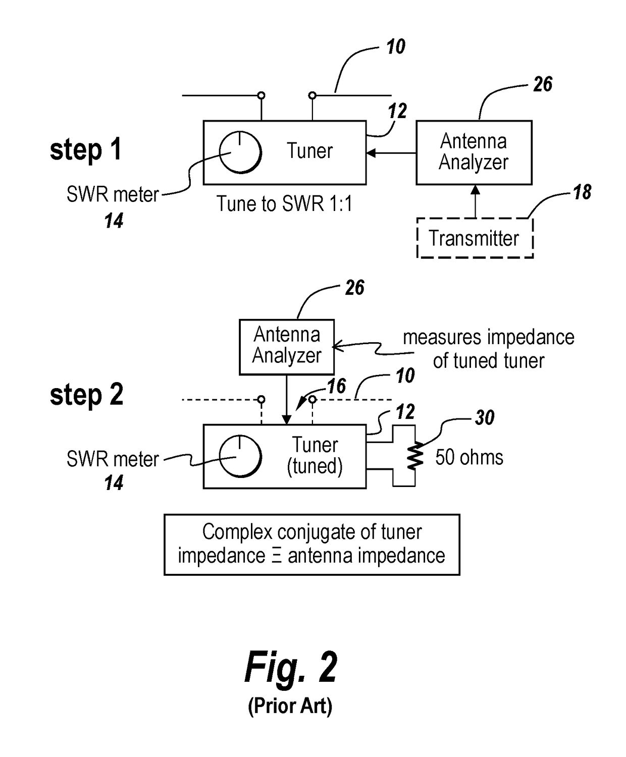
[0033]Referring now to FIG. 1, in the prior art, in order to obtain the antenna input impedance at the feed point of an antenna which is remote from the tuner, in Step 1 of this process, antenna 10 is coupled to a tuner 12 which has an SWR meter 14 indicating the SWR measured at the tuner. Antenna 10 is coupled to tuner 12 at antenna input terminals 16, with a transmitter 18 coupled to the transmitter input 20 of tuner 12.

[0034]In Step 2 of this prior art process, antenna 10 is disconnected from the antenna input terminal 16 of tuner 12 and a series RC and / or an RL circuit having a variable capacitor 22 and / or a variable inductor (not shown) and a variable resistor 24 is connected in series across the antenna input terminals 16 of tuner 12. At the same time, transmitter 18 is disconnected from tuner 12 and an antenna analyzer 26 is connected to the transmitter input terminals of tuner 12.

[0035]The capacitive element 22 and / or inductive element (not shown) and resistive element 24 ar...


PUM


Abstract

A system for remotely measuring antenna input impedance utilizing an automatic antenna tuner in which for any tuner, the tuner input impedance may be established by the values of the components in the circuit at the time that the SWR is at a minimum, with these values being automatically available in terms of the components that are switched in to achieve low SWR. Once having established the input impedance to the tuner, the complex conjugate of the tuner input impedance yields the antenna input impedance, with antenna input impedance sensed at full power at a position remote from the antenna input.

Description

FIELD OF INVENTION[0001]This invention relates to the measurement of antenna impedance and more particularly to remotely sensing antenna impedance at the antenna feed point utilizing an automatic antenna tuner.BACKGROUND OF THE INVENTION[0002]It has long been a problem to measure antenna impedance at the feed point of an antenna when the antenna has been installed or is in place and is remote from the transmitter to which is coupled. In order to be able to transmit efficiently, it is important to be able to match the output impedance of a transmitter to the input impedance of the antenna and to do so antenna tuners are interposed between the feed point of the antenna and the transmitter output. Antennas typically have a transmission line that connects them to the output of the transmitter and the antenna tuners only function to sense impedance at the transmitter end of the transmission line and match that impedance to the output impedance of the transmitter.[0003]While this couples ...

Claims


Application Information

Patent Timeline
IPC IPC(8): G01R29/10H04B17/12
CPCH04B17/12G01R29/10H04B17/104H04B17/23H04B1/40H04B17/13H01Q1/50
Inventor JUE, MARTIN F.
Owner JUE MARTIN F
Why Eureka
Try Eureka