Electric machine unit with groove for receiving a protective cap

Inactive Publication Date: 2018-02-01
SEG AUTOMOTIVE GERMANY GMBH
View PDF11 Cites 2 Cited by
  • Summary
  • Abstract
  • Description
  • Claims
  • Application Information

AI Technical Summary

Benefits of technology

[0012]The groove preferably has alignment means which align the protective cap relative to the electric machine with respect to a rotation about an axis perpendicular to

Problems solved by technology

Specifically, it has been found that the fixing at the top side is on its own not sufficient to suppress vibrations, because the side walls

Method used


Image

  • Electric machine unit with groove for receiving a protective cap
  • Electric machine unit with groove for receiving a protective cap
  • Electric machine unit with groove for receiving a protective cap

Examples


Example

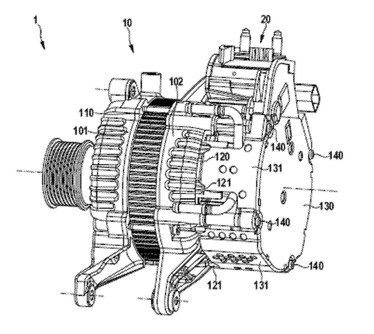
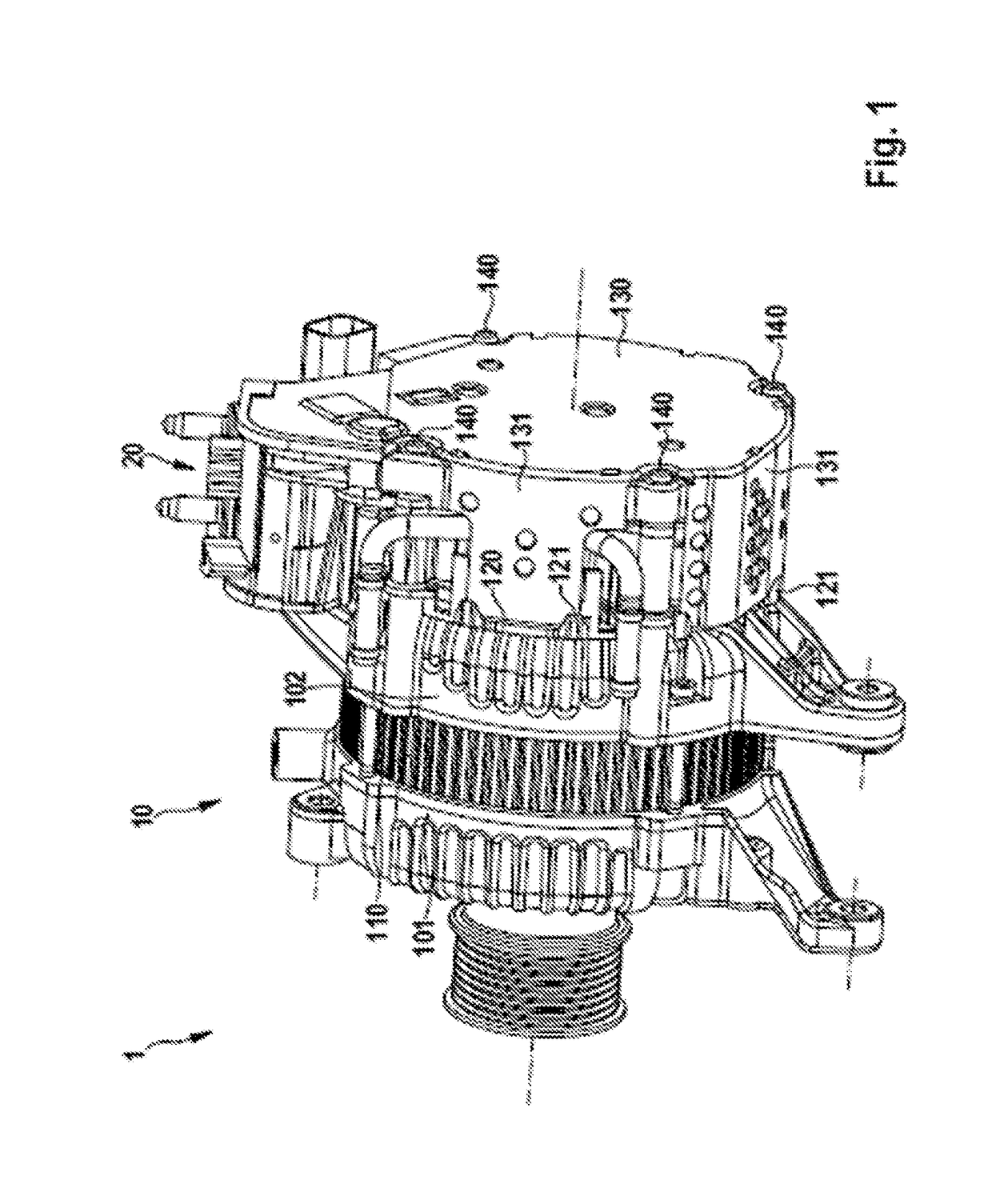
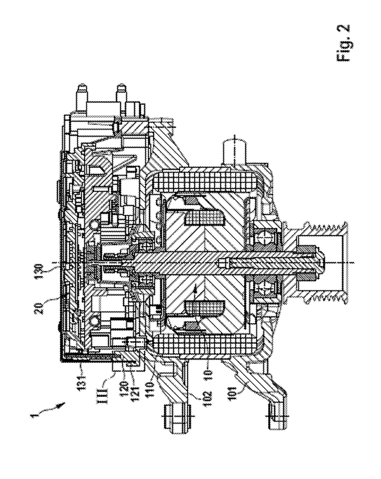
[0026]Firstly, on the basis of FIGS. 1 to 5, an overall description will be given of a preferred embodiment of an electric machine unit 1 according to the invention, with an advantageous refinement illustrated in FIGS. 6 and 7 then being described.

[0027]The electric machine unit 1 is for example in the form of a boost recuperation machine (BRM) for a boost recuperation system (BRS) and has a claw-pole machine 10 as an electric machine and power electronics 20 mounted thereon. Said electric machine unit has for example a rated voltage of 48 V.

[0028]The housing of the claw-pole machine 10 is composed substantially of two bearing plates 101 and 102 with mounting arms for the fastening of the electric machine unit for example to the internal combustion engine. The bearing plates fix the stator 110.

[0029]Between the claw-pole machine 10 and the power electronics 20 there is situated a connection plate 120. The connection plate 120 is in this case in the form of a plastics injection-molde...


PUM


Abstract

An electric machine unit (1) having an electric machine (10), having power electronics (20) mounted thereon, and having a protective cap (130) for the power electronics (20), wherein the protective cap (130) has a top side and has a side wall (131) with a free edge (132), wherein the side wall (131) of the protective cap (130) is, at the free edge (132), arranged at least in sections in a groove (121).

Description

BACKGROUND OF THE INVENTION[0001]The present invention relates to an electric machine unit having an electric machine and having power electronics mounted thereon.[0002]Electric machine units having an electric machine and having power electronics mounted thereon are used for example in motor vehicles as starters or generators or in combined form as starter-generators or so-called boost recuperation machines (BRM). They may have, for example, a separately excited electric machine with rotor winding (exciter winding) and stator winding and, as power electronics, a power converter with regulator (e.g. generator regulator or field regulator) which is connected downstream of the stator winding and which regulates the voltage generated by the electric machine and / or the torque generated by the electric machine.[0003]To protect the electrical phases against being touched, the power electronics should be covered by means of a protective cap. In the case of relatively high voltages, such as...

Claims


Application Information

Patent Timeline
IPC IPC(8): H02K5/22H02K11/33H02K1/14H02K5/24H02K11/02
CPCH02K5/22H02K5/24H02K11/02Y10S903/902H02K11/33B60K6/485H02K1/145H02K5/02H02K5/04
Inventor HOCH, ANDREASSCHROEDER, BERNDKAEPPLE, MARIOHENGER, MARTINCUESTA, MIGUEL CIRUJANO
Owner SEG AUTOMOTIVE GERMANY GMBH
Why Eureka
Try Eureka