

Display apparatus and illumination apparatus, and light emitting element and semiconductor device
a technology of light emitting elements and display apparatus, which is applied in the direction of semiconductor devices for light sources, lighting and heating apparatus, etc., can solve the problems of non-uniform display pictures and degradation of quality of display apparatuses utilizing leds as light emitting elements, and achieve the effect of reducing the influence of display
Inactive Publication Date: 2018-02-08
SONY SEMICON SOLUTIONS CORP
View PDF4 Cites 34 Cited by
- Summary
- Abstract
- Description
- Claims
- Application Information
AI Technical Summary
Benefits of technology
The disclosed patent text describes a display apparatus and an illumination apparatus that make it possible to enhance quality and reduce deviation of viewing angle characteristics. This is achieved by using light emitting elements that have different peak wavelengths in different wavelength bands. The display apparatus includes pixels that have two or more adjacent light emitting elements, while the illumination apparatus includes unit groups of pixels that have the same light emitting elements. Additionally, the first light emitting element has a larger second electrode or a variable thickness of the first electrode, which corrects deviation of the light emitted from the active layer and reduces the influence of wavelength variations. Overall, this technology improves image quality and reduces color distortion while ensuring the desired brightness and hues.
Problems solved by technology
Accordingly, the display apparatus utilizing the LEDs as the light emitting elements has a disadvantage of non-uniformity of displayed pictures.
Furthermore, with such light emitting elements disposed in each pixel, desired hues and brightness are not represented, causing degradation in quality.
Method used
View moreImage
Smart ImageViewing Examples

Examples
modification examples 1-4 (
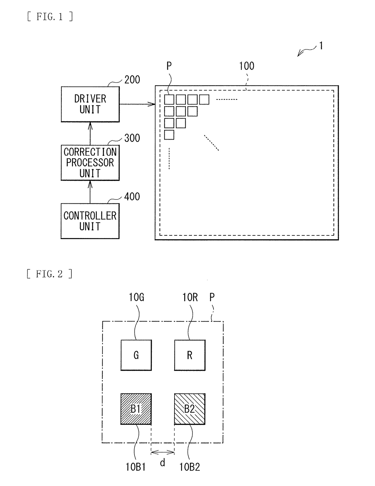
2. Modification Examples 1-4 (examples of variations in which the two kinds of the blue light emitting elements are disposed in the pixel)
modification examples 5-7 (
3. Modification Examples 5-7 (examples of cases where the two kinds of the blue light emitting elements are disposed in a pixel group)
modification example 8 (
4. Modification Example 8 (an example of a case where two kinds of green light emitting elements and two kinds of red light emitting elements are disposed as well)
Login to View More PUM
 Abstract
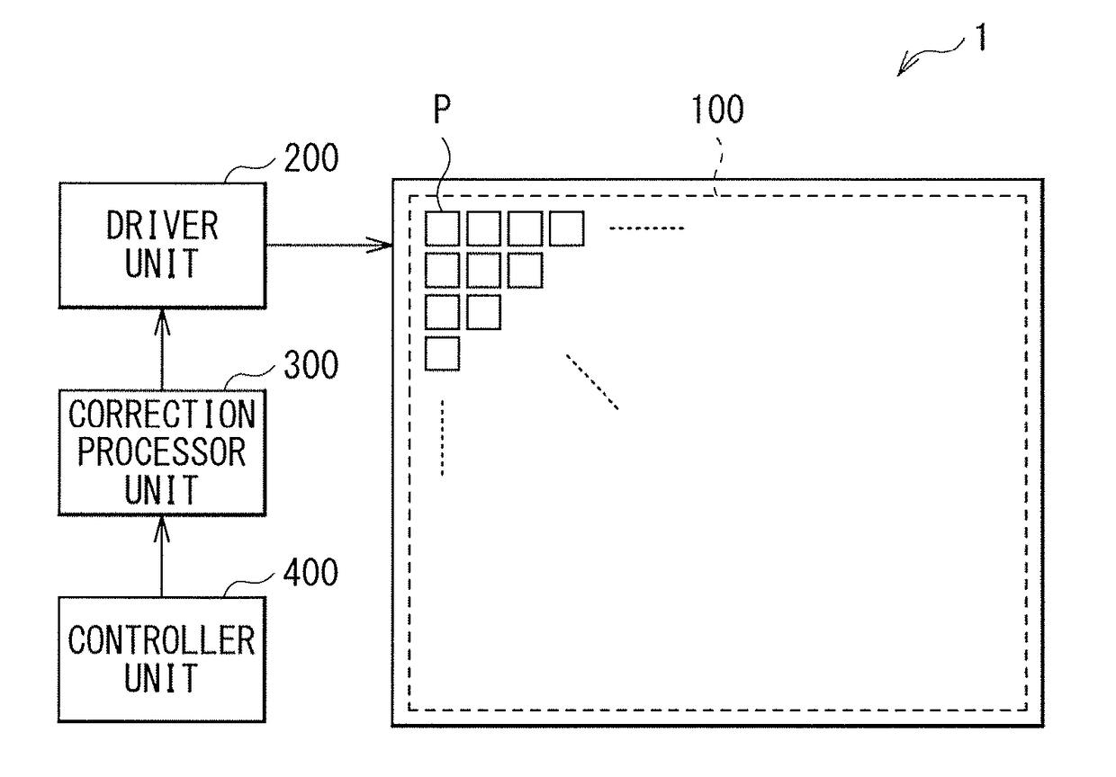
A display apparatus according to one embodiment of the disclosure includes pixels in a plurality. The pixels are two-dimensionally disposed, and the pixels each include light emitting elements of at least a first primary color. The pixels each or pixel groups each include, as the light emitting elements of the first primary color, a first light emitting element and a second light emitting element that have peak wavelengths of light emission in different wavelength bands from each other. The pixel groups each include two or more adjacent ones of the pixels.
Description
TECHNICAL FIELD[0001]The disclosure relates to a display apparatus and an illumination apparatus that utilize light emitting elements in primary colors, and a light emitting element that emits light in a stacking direction of semiconductors and a semiconductor device that includes the light emitting element.BACKGROUND ART[0002]In recent years, there have been spreading illumination apparatuses and display apparatuses that are constituted by a group of a plurality of light emitting diodes (LEDs). Among them, LED displays are drawing attention as light-weighted and low-profile displays, with various improvements having been made in, for example, enhancement in light emission efficiency. The LED displays utilize the LEDs as display pixels.[0003]For example, display apparatuses (LED displays) using three primary colors such as R (red), G (green), and B (blue) have high luminance and high color purity, and are in wide use as large-sized indoor or outdoor displays (For example, refer to P...
Claims
Login to View More Application Information
Patent Timeline
 IPC IPC(8): H01L27/15H01L33/36F21V19/00H01L33/46
CPCH01L33/46H01L33/36F21V19/0015F21Y2113/13F21Y2115/10F21Y2105/18H01L27/156H01L29/41H01L33/38H01L25/0753H01L33/20H01L33/405
InventorOHMAE, AKIRAKATAOKA, YUSUKEOHASHI, TATSUONISHINAKA, IPPEIBIWA, GOSHI
OwnerSONY SEMICON SOLUTIONS CORP