Method of Producing a Liquid Cooled Coldplate

a cold plate and liquid cooling technology, applied in the direction of liquid/solution decomposition chemical coating, electrical apparatus construction details, semiconductor/solid-state device details, etc., can solve the problems of plugging of the cold plate and not being particularly clean, and achieve the effect of less flow volume, better temperature consistency, and better cooling

Active Publication Date: 2018-02-08
WIELAND MICROCOOL LLC
View PDF0 Cites 17 Cited by
  • Summary
  • Abstract
  • Description
  • Claims
  • Application Information

AI Technical Summary

Benefits of technology

[0002]Certain electronic devices generate heat as they operate, and in some cases this heat has to be removed or dissipated for the device to continue operating properly. Several techniques have been used to cool electronic equipment. Examples include fans, which are used to blow air over electronic equipment. This air serves to convectively cool the electronic equipment with normal ambient air. Other techniques that have been used include liquid cold plates. Liquid cold plates are plates with channels through which liquid flows. The electronic equipment is mounted in contact with a liquid cold plate and the heat generated by the electronic equipment is transferred to the liquid coolant inside the plate. This can provide better cooling than the convective cooling provided by a fan with considerably less flow volume. It can also provide better temperature consistency with less acoustic noise.

Problems solved by technology

Some important factors include cost of production and ease of producing relatively large quantities.
In some applications, the coolant may not be particularly clean, which can result in plugging of the cold plate.

Method used


Image

  • Method of Producing a Liquid Cooled Coldplate
  • Method of Producing a Liquid Cooled Coldplate
  • Method of Producing a Liquid Cooled Coldplate

Examples


Embodiment Construction

Heat Transfer Fundamentals

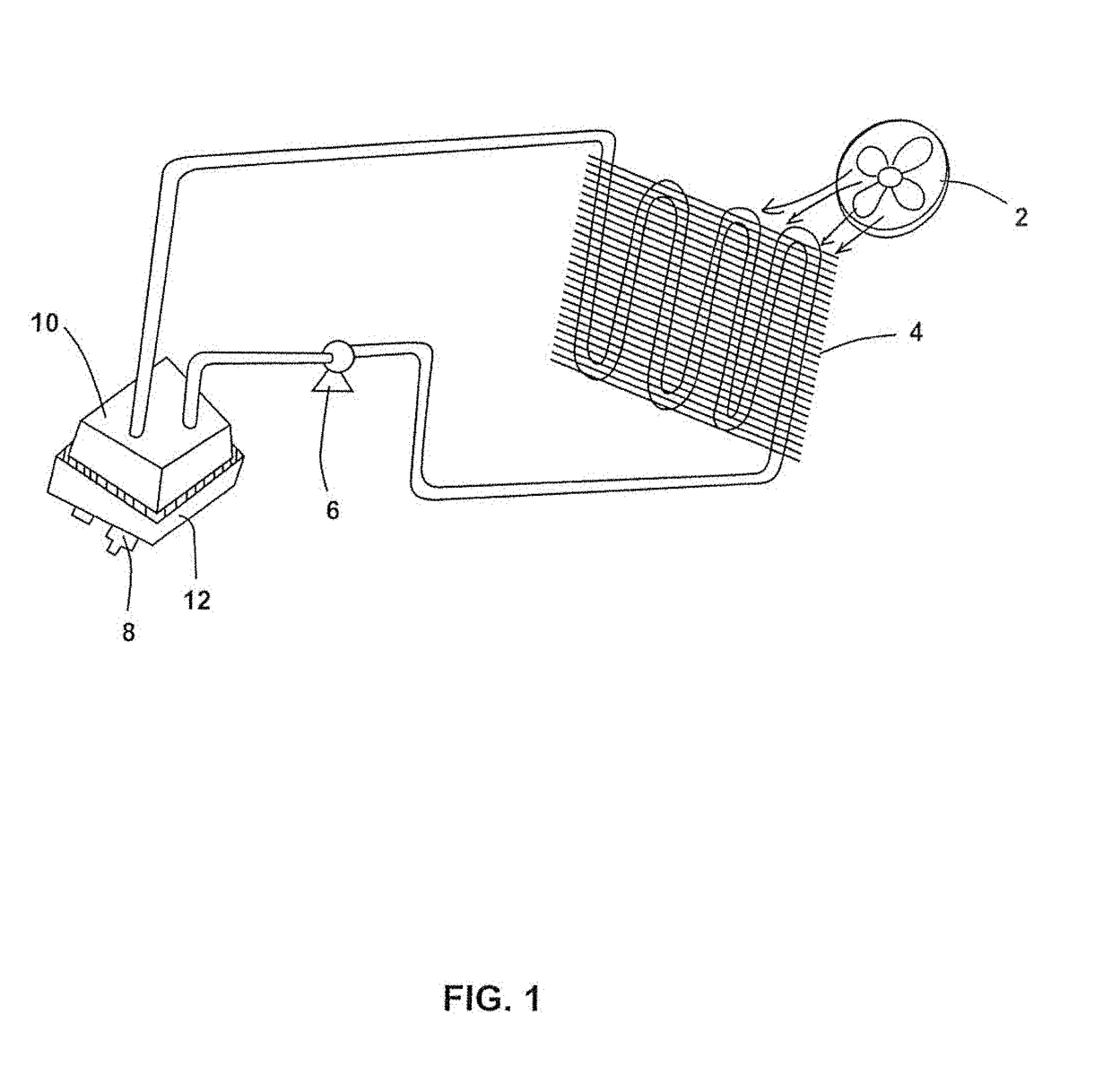
[0023]There are several ways to cool electronic equipment. Often times, electronic equipment is cooled with fans which blow air over the electronic equipment. This air provides convective cooling which does help to control the heat generated by the electronic equipment. However, liquid cooling can provide greater cooling capacity than air flow in many situations.

[0024]Liquids can provide better cooling than gases for several reasons. For example, liquids are denser than gases so more thermal mass is available to absorb heat from the electronic equipment. Also, liquids generally have higher thermal conductivities so heat will transfer into and through the liquid more rapidly than heat will transfer into and through a gas. Furthermore, liquids tend to have a higher specific heat than gases so a set quantity of liquid will absorb and transfer more heat than a comparable amount of gas. Because of this, when electronic equipment is utilized which produces large ...


PUM

PropertyMeasurementUnit
angleaaaaaaaaaa
angleaaaaaaaaaa
thicknessesaaaaaaaaaa

Abstract

A liquid cooled coldplate has a tub with an inlet port and an outlet port and a plurality of pockets recessed within a top surface of the tub. Each pocket has a peripheral opening and a ledge, the ledge disposed inwardly and downwardly from the peripheral opening. The inlet port and outlet port are in fluid communication with the pocket via an inlet slot and an outlet slot. A plurality of cooling plates are each received by a pocket and recessed within the pocket. Each cooling plate comprises an electronics side for receiving electronics and enhanced side for cooling the cooling plate. The enhanced side of the cooling plate comprises a plurality of pins formed by micro deformation technology. The tub may be formed by extrusion.

Description

REFERENCE TO RELATED APPLICATIONS[0001]The present application claims priority to U.S. Provisional Patent Application 62 / 162,195, filed May 15, 2015, titled “Liquid Cooled Coldplate.” The present application also claims priority to U.S. Provisional Patent Application No. 62 / 332,733, filed May 6, 2016, titled “Liquid Cooled Coldplate with Clad Fin Plates.” The present application is also a continuation-in-part of, and claims priority to, U.S. Non-Provisional patent application Ser. No. 15 / 155,568, filed May 16, 2016, titled “Method of Producing a Liquid Cooled Coldplate,” which is a continuation-in-part of U.S. Non-Provisional patent application Ser. No. 14 / 307,074, filed Jun. 17, 2014, titled “Electronics Substrate with Enhanced Direct Bonded Metal,” which is a continuation of, and claims priority to, U.S. Non-Provisional patent application Ser. No. 13 / 191,281, filed Jul. 26, 2011, titled “Electronics Substrate with Enhanced Direct Bonded Metal,” which claims priority to U.S. Provis...

Claims


Application Information

Patent Timeline
Patent Type & Authority Applications(United States)
IPC IPC(8): H05K7/20B21J5/12H01L21/48
CPCH05K7/20254H05K7/20927H01L21/4878B21J5/12H05K3/0061H05K1/0306B21J5/068C23C18/1651C23C18/32H01L23/3735H01L23/473H01L25/072H01L2924/0002Y10T29/49002Y10T29/49124Y10T29/4913Y10T29/49167Y10T83/0341H01L2924/00Y10T29/49169
Inventor REEVES, MATTHEW A.HOLLAND, ROBERT SCOTTLOONG, SY-JENQ
Owner WIELAND MICROCOOL LLC
Why Eureka
Try Eureka