
Specimen observation apparatus and specimen observation method

a technology of specimen observation and apparatus, applied in the field of specimen observation apparatus and specimen observation method, can solve problems such as enlarged apparatus

Active Publication Date: 2018-02-15
EVIDENT CORP
View PDF2 Cites 7 Cited by
  • Summary
  • Abstract
  • Description
  • Claims
  • Application Information

AI Technical Summary

Benefits of technology

The present invention describes a specimen observation apparatus that uses an illumination optical system to apply illumination light to a specimen, and an imaging optical system to capture an optical image of the specimen. The image is formed in a state where the position of the specimen and the focus position of the imaging optical system are different, which results in an optical image that is out of focus at some points. The invention also includes a method for acquiring an electronic image of the specimen and a subtraction step to obtain the image in a state where the position of the specimen and the focus position of the imaging optical system are different, resulting in an optical image that is out of focus at some points. The technical effects of this invention are improved image quality and reduced blurring of the optical image, which provides a more accurate and reliable means of observing specimens.

Problems solved by technology

However, since the observation apparatus as described above is based on observation with transmitted illumination, there has been a problem in that the apparatus is enlarged.

Method used


Image

  • Specimen observation apparatus and specimen observation method
  • Specimen observation apparatus and specimen observation method
  • Specimen observation apparatus and specimen observation method

Examples


first embodiment

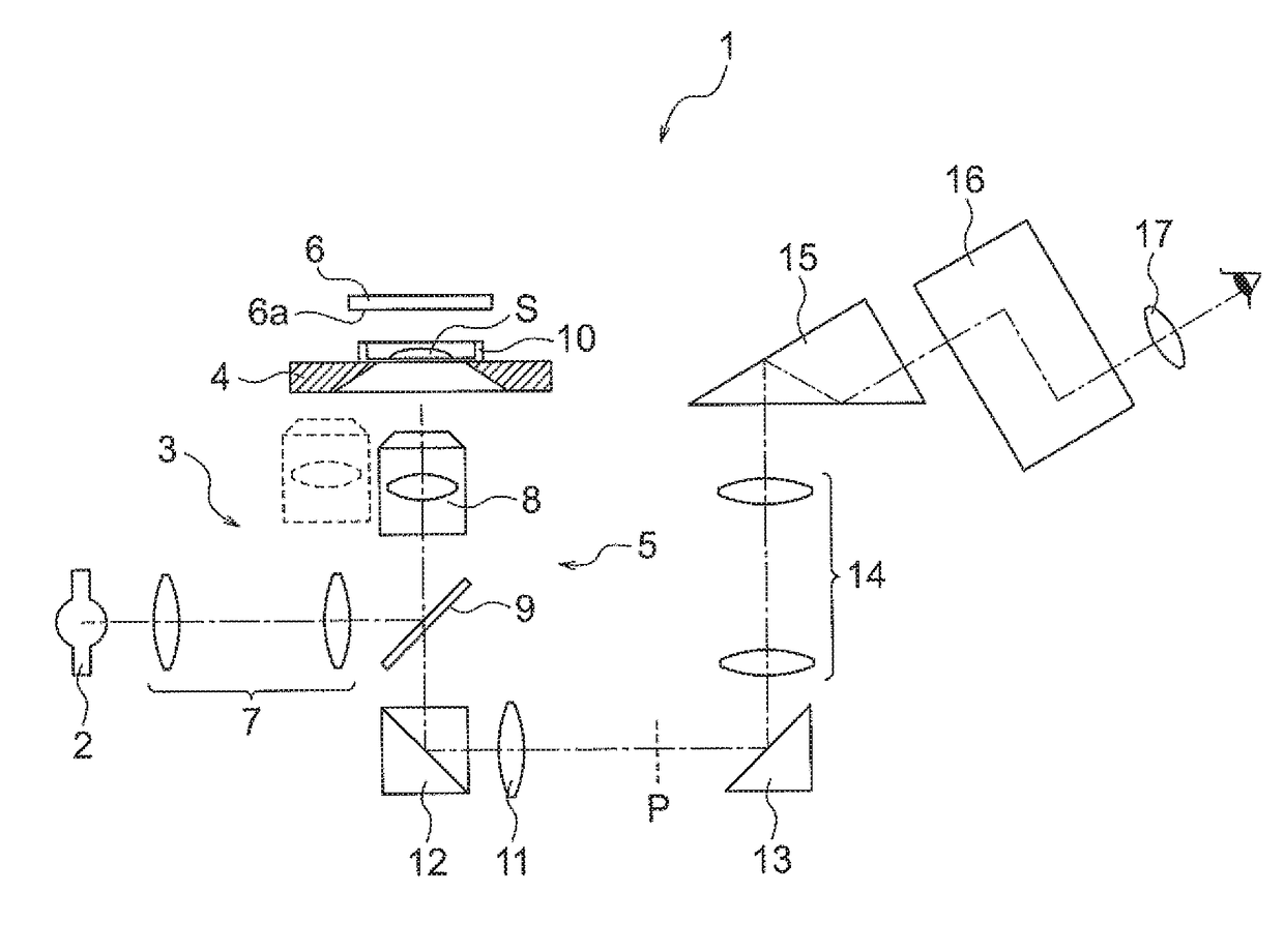
[0051]A specimen observation apparatus 1 of the first embodiment is an apparatus using an inverted microscope, for example. The specimen observation apparatus 1 includes, as the basic configuration, a light source 2, an illumination optical system 3, a stage 4, an imaging optical system 5, and a reflection member 6.

[0052]The light source 2 is located below the stage 4 in the figure. Illumination light is emitted from the light source 2. For the light source 2, for example, a halogen lamp, a xenon lamp, a mercury lamp, a laser, or a light emitting diode is used.

[0053]The illumination light emitted from the light source 2 enters the illumination optical system 3. The illumination optical system 3 is located below the stage 4 in the figure. The illumination optical system 3 is configured by a light collecting optical system 7 and an objective lens 8. As described later, the objective lens 8 forms the imaging optical system 5 together with a tube lens 11. In this manner, the objective l...

second embodiment

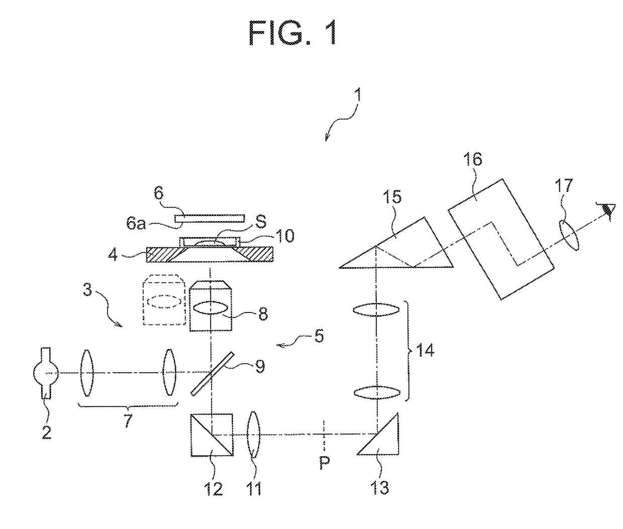
[0093]FIG. 2 is a diagram illustrating the configuration of a specimen observation apparatus of the The same configuration as in FIG. 1 is denoted by the same number and its detailed description is omitted.

[0094]In the specimen observation apparatus of the second embodiment, an optical image of a specimen can be converted into an electronic image and observed. Therefore, a specimen observation apparatus 20 includes a mirror 21, an image pickup device 22, and an image processing device 23 in addition to the above-mentioned basic configuration.

[0095]Light from the specimen S passes through the objective lens 8 and the half mirror 9 and enters the mirror 21. Light reflected by the mirror 21 is condensed by the tube lens 11.

[0096]In the state in which the position of the specimen S and the focus position are different from each other, an optical image having a contrast is formed at the position P. Since the image pickup device 22 is disposed at the position P, the image of the specimen...

fourth embodiment

[0218]As illustrated in FIG. 16, the specimen observation method of the fourth embodiment includes Step S50 for acquiring an electronic image for correction and Step S50 for subtracting the electronic image for correction from the electronic image in addition to the acquisition step S10 and the subtraction step S20.

[0219]In the specimen observation method of the fourth embodiment, Step S50 for acquiring the electronic image for correction is executed before the reflection member is disposed on the specimen. In Step S50, the reflection member is not disposed on the specimen. In this case, since a large portion of the illumination light just passes through the specimen, a large portion of the illumination light does not enter the imaging optical system again. However, since part of the illumination light is reflected by a bottom surface of the container, the reflected light from the bottom surface of the container enters the imaging optical system.

[0220]Since the reflected light from ...


PUM


Abstract

A specimen observation apparatus includes: a light source; an illumination optical system; a stage; an imaging optical system; and a reflection member disposed at a position opposed to the imaging optical system across the stage. The illumination optical system is disposed so as to apply illumination light from the light source to a specimen. The imaging optical system is disposed at a position at which the illumination light that is transmitted through the specimen and thereafter reflected by the reflection member to be transmitted through the specimen again enters, and is configured to form an optical image of the specimen. The optical image is formed in a state in which a position of the specimen and a focus position of the imaging optical system are different from each other.

Description

CROSS-REFERENCE TO RELATED APPLICATION[0001]The present application is a continuation application of International Application No. PCT / JP2015 / 065152 filed on May 20, 2015, the entire contents of which are incorporated herein by reference.BACKGROUND OF THE INVENTION[0002]Field of the Invention[0003]The present invention relates to a specimen observation apparatus and a specimen observation method.[0004]Description of the Related Art[0005]In recent years, in order to elucidate the life phenomenon of living cells in the cellular level, a method of observing the behavior of the cells over time while continuing cell cultivation, that is, what is called time-lapse imaging has become widely used. In the time-lapse imaging, an observation apparatus in which an incubator and a phase contrast microscope are combined is used. However, since the observation apparatus as described above is based on observation with transmitted illumination, there has been a problem in that the apparatus is enlar...

Claims


Application Information

Patent Timeline
Patent Type & Authority Applications(United States)
IPC IPC(8): G02B21/14G02B21/36
CPCG02B21/14G02B21/367C12Q1/02C12M41/46
Inventor SUZUKI, YOSHIMASA
Owner EVIDENT CORP
Learn More