High dose output, through transmission & relective target x-ray system and methods of use

a relective target and high dose output technology, applied in the field of xray tube technology, can solve the problems of reducing the symmetry limited utilization of x-ray photons, and the watt density loading etc., and achieve the effect of reducing the watt density of the target anode before melting, and reducing the sensitivity of the radiation field

Active Publication Date: 2018-02-15
RAD SOURCE TECH
View PDF8 Cites 3 Cited by
  • Summary
  • Abstract
  • Description
  • Claims
  • Application Information

AI Technical Summary

Benefits of technology

[0008]Briefly described, in example embodiment, the present apparatus overcomes the above-mentioned disadvantage, and meets the recognized need for a high dose output, through transmission target x-ray tube and methods of use including, in general, an x-ray tube for accelerating electrons under a high voltage potential, said x-ray tube includes an evacuated housing that is sealed, a through transmission target anode structure disposed on said housing, said anode structure configured in a hemispherical shape having a geometric center, a cathode structure disposed in said housing, said cathode configured to deflect the electrons toward said hemispherical anode, a filament disposed in said housing, said filament positioned proximate said geometric center of said hemispherical shape and between said anode and said cathode, an evacuated housing, said housing configured to vacuum seal there in said anode, said cathode, and said filament, and, thus, such x-ray tube functions to provide a large surface area anode target to dissipate heat and to enable use of different z materials to take advantage of the characteristic x-ray with improved radiation output, lower melting point, and lower electrode potential required to produce higher output radiation.

Problems solved by technology

The primary limitation of this type of tube is the watt density loading of the target anode before melting occurs, limited utilization of generated x-ray photons and the symmetry of the resulting radiation field.
The two requirements are contrary and cannot be resolved in the traditional tube design.
In addition the reflective nature of the emitted radiation is asymmetrical about a beam centerline and is grossly inefficient for X-ray irradiation applications.

Method used


Image

  • High dose output, through transmission & relective target x-ray system and methods of use
  • High dose output, through transmission & relective target x-ray system and methods of use
  • High dose output, through transmission & relective target x-ray system and methods of use

Examples


Embodiment Construction

[0049]In describing the exemplary embodiments of the present disclosure, as illustrated in FIGS. 1-3, 3.1, 4-10, 11A, 11B, 12-13 specific terminology is employed for the sake of clarity. The present disclosure, however, is not intended to be limited to the specific terminology so selected, and it is to be understood that each specific element includes all technical equivalents that operate in a similar manner to accomplish similar functions. The examples set forth herein are non-limiting examples, and are merely examples among other possible examples.

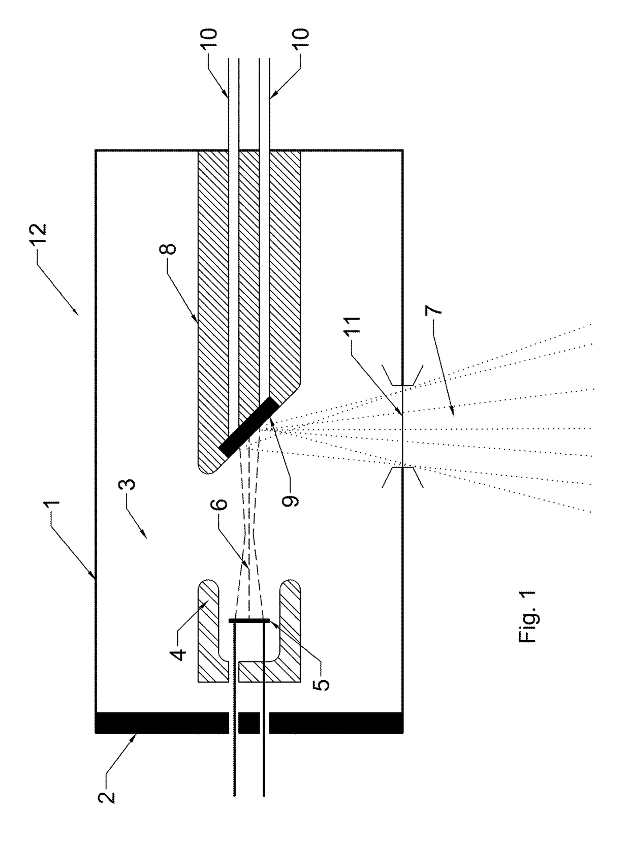
[0050]Referring now to FIG. 1 there is illustrated a schematic cross sectional representation of Coolidge type X-ray tubes 12, shown in FIG. 1, includes x-ray tube housing 1, which may be glass or metal, high voltage insulation 2, and a vacuum dielectric 3 contained therein x-ray tube housing 1. In a Coolidge tube X-ray photons, shown as a fanned output radiation pattern 7, are generated by impinging an electron beam emanating from fila...


PUM


Abstract

A high dose output, through transmission and reflective target x-ray tube and methods of use includes, in general an x-ray tube for accelerating electrons under a high voltage potential having an evacuated high voltage housing, a hemispherical shaped through and reflective transmission target anode disposed in said housing, a cathode structure to deflect the electrons toward the hemispherical anode disposed in said housing, a filament located in the geometric center of the anode hemisphere disposed in said housing, a power supply connected to said cathode to provide accelerating voltage to the electrons.

Description

CROSS REFERENCE TO RELATED APPLICATIONS[0001]To the full extent permitted by law, the present United States Non-provisional patent application is a Continuation-in-Part of, hereby claims priority to and the full benefit of U. S. Non-Provisional patent application entitled “High Dose Output, Through Transmission Target X-Ray System and Methods of Use,” filed on Dec. 31, 2014, having assigned Ser. No. 14 / 587,634.TECHNICAL FIELD[0002]The disclosure relates generally to x-ray tube technology and more specifically it relates to x-ray tubes with specific anode, cathode, filament configurations and material choices to produce high dose x-ray output.BACKGROUND[0003]In many typical state of the art X-ray tubes, a cathode assembly and an anode assembly are vacuum sealed in a glass or metal envelope. Electrons are generated by at least one cathode filament in the cathode assembly. These electrons are accelerated toward the anode assembly by a high voltage electrical field. The high energy elec...

Claims


Application Information

Patent Timeline
Patent Type & Authority Applications(United States)
IPC IPC(8): H01J35/06H01J35/10
CPCH01J35/06H01J35/105H01J2235/087A61B6/40A61B6/482H01J1/16H01J1/40H01J1/94H01J35/32H01J2235/16A61B6/4488H01J2235/085H01J35/186H01J35/116H01J35/066H01J35/08
Inventor AUSBURN, PHILLIP KENT
Owner RAD SOURCE TECH
Why Eureka
Try Eureka