
Tension Structure For The Spatial Positioning Of Functional Elements

a functional element and tension structure technology, applied in the field of structure, can solve the problems of becoming an increasingly difficult technological challenge, imposing practically insurmountable challenges, and reducing the range of visible light (wavelength down to 1 micron)

Inactive Publication Date: 2018-02-15
TENTGUILD ENG CO
View PDF0 Cites 10 Cited by
  • Summary
  • Abstract
  • Description
  • Claims
  • Application Information

AI Technical Summary

Benefits of technology

The present invention aims to provide a simple and efficient structure to hold form-retentive functional elements that are cooperatively functional in their operational state in a predetermined relative spatial arrangement. This means that the functional elements do not collapse but essentially maintain their form even without any external form-m maintaining forces. The invention also provides new stowage solutions, deployable structures that can open up to their operational configuration in ways different from those enabled by prior art technologies, new kinds of robust structural forms, and still higher precision for such purposes. Additionally, the invention allows for easily adjustable structures.

Problems solved by technology

This becomes an increasingly difficult technological challenge as higher and higher EM frequencies (with associated lower and lower wavelengths) are considered with the advancement of the state of the art.
Radar radiation (wavelengths down to 1 mm) can already be difficult to manage in some cases.
The sufficiently precise management of visible light (wavelengths down to 1 micron) already imposes practically insurmountable challenges in many cases.
For X-ray (down to nanometer-class wavelengths) even providing proper and efficient reflective surfaces can be a problem in space, where structural and equipment weight are also a prohibitively critical concern.
Although aggressive innovations in electronics and signal processing technology (e.g., synthetic aperture radar, phased array antenna technology, very large baseline technology for interferometry) have reduced some dimensional needs for certain devices, device size even for those application can still be large.
Larger dimensions make the device and its components much more difficult to fabricate.
Furthermore, the larger a structure, the more sensitive it generally is to effects of the space environment (extreme thermal effects, and dynamic disturbances by pointing and orbit adjustments) and render the challenge of packaging more difficult (the device has to autonomously open up to its operating dimensions from a state compact enough to fit the shroud of the launch vehicle, e.g., the tip of a rocket).
Despite the enormous variety of deployable technologies already developed (self-deployment by elastic means, deployment by hinged-actuated mechanics, by pressurization, by centrifugal force, by gravity gradient effects, etc.) the deployment problem for most precision devices managing EM radiation patterns is far from being sufficiently solved, especially for low wavelengths (high frequencies).
For low wavelengths, the sheer structural deformations as a result of environmental effects (thermal changes, disturbances) and geometric repeatability (precision) issues of various deployable components (such as hinges, inflatable elements) by themselves can easily be greater than the precision required of the device, handicapping overall precision.
Such mechanical elements, although enabling the deployment process, also limit stowage options and overall precision.
For example, a hinge between two device elements (e.g., two mirror segments) allows the device to be articulated (“folded”), but it also severely constrains how the joined components can be placed in stowage because they both are locked to the hinge.
Further, the hinge itself can introduce geometric imprecision into the deployed device.
Thus, although much progress in hinge, flexure, articulation, truss, and actuation technology has been made, technology still has very severe—in fact, prohibitive—limitations.
However, despite aggressive research worldwide, certain design paradigms have not yet been questioned.
Consequently, the design of a stowage and of deployment kinematics becomes difficult to engineer, and the precision of the deployment device ends up partly or fully depending on the precision of the used rigid (compression) elements and on the flexed or hinged stowage articulation mechanisms.
This philosophy results in structures the deployment of which can be closely controlled, but the design itself of stowage itself remains very severely constrained.
Within the context of functional device elements of stable shapes, the use of stiff and precise tension (cord, film, or fabric-like) elements is typically limited to complementing rigid structures that govern the construction, or to simply locking solid elements to each other.
Consequently, such preloading cannot robustly provide structural precision and uninterrupted integrity against environmental effects.
By virtue of relying on weak force fields, such systems are utterly unfit for precision applications.
Their potential use is limited to solar sails and solar concentrators in very specific circumstances within the realm of so-called “gossamer” structures, to be fabricated one day in the distant future.
Such structures, by definition, are applicable to control a planar device configuration only; their extension to enforce a spatial arrangement of functional device elements is impossible.
Further, the stretched shape is not robustly precise, because they resist lateral perturbations only by so-called second order stiffness (stiffness proportional to the magnitude of tension).
Any of these (tension) structures would simply collapse if they weren't pretensioned.

Method used


Image

  • Tension Structure For The Spatial Positioning Of Functional Elements
  • Tension Structure For The Spatial Positioning Of Functional Elements
  • Tension Structure For The Spatial Positioning Of Functional Elements

Examples


Embodiment Construction

[0023]An object of the present invention is to provide a simple and efficient structure to hold form-retentive functional elements that are cooperatively functional in their operational state in a predetermined relative spatial arrangement. Form-retentiveness means that the functional elements do not collapse but essentially maintain their form even without any external form-maintaining forces. A further object is to provide structures with form-retentive functional elements and with new stowage solutions that are not possible with prior art technologies. A further object is to provide deployable structures that can open up to their operational configuration in ways different from those enabled by prior art technologies. A further object is to provide new kinds of robust structural forms, and a still further object is to achieve high precision for such purposes. A still further object is to provide easily adjustable structures.

[0024]The objects according to the invention have been r...


PUM


Abstract

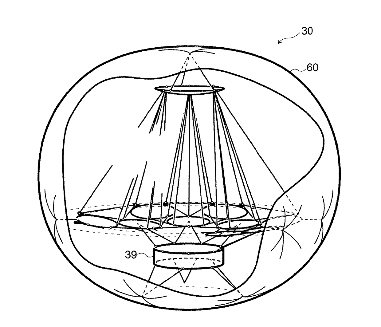
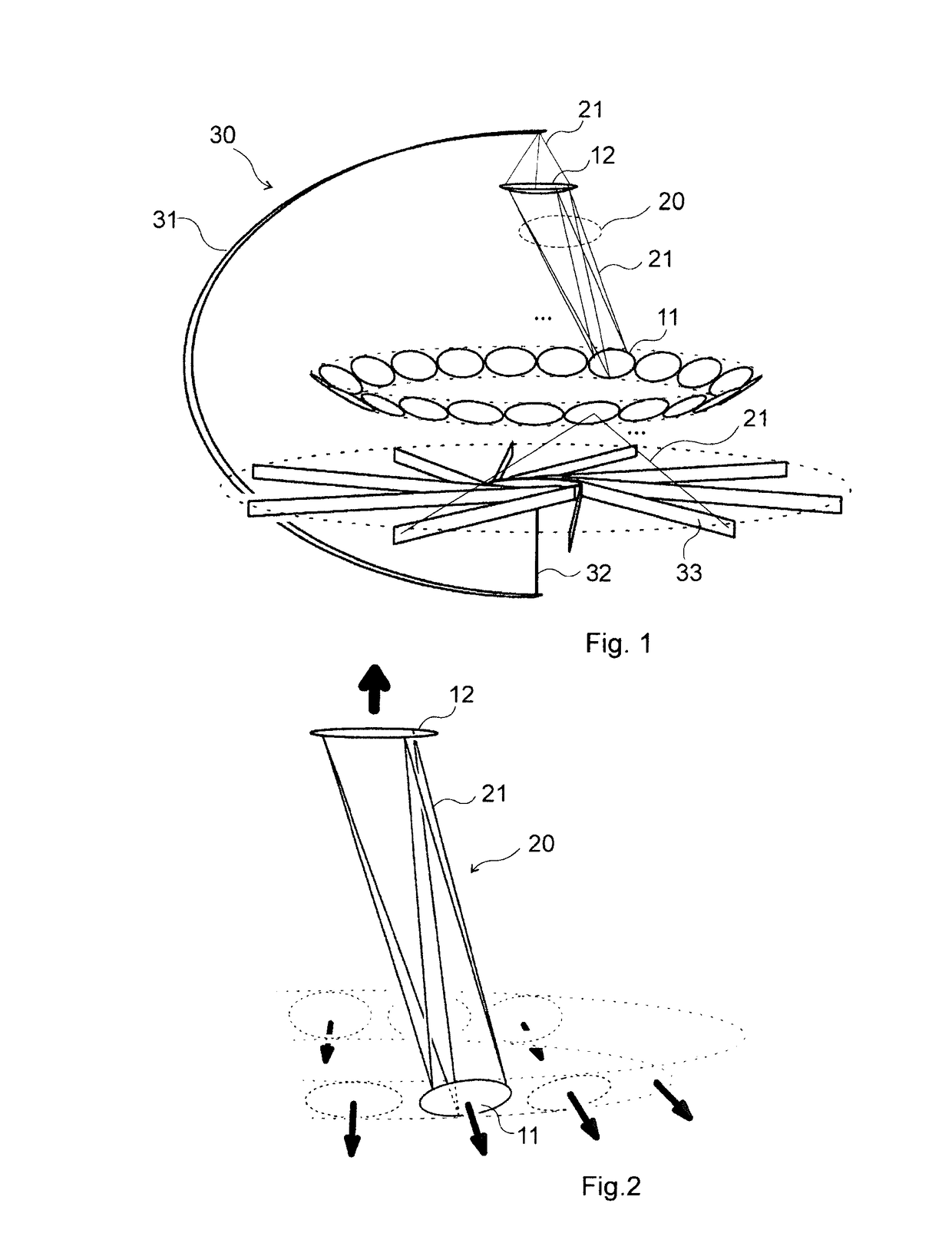
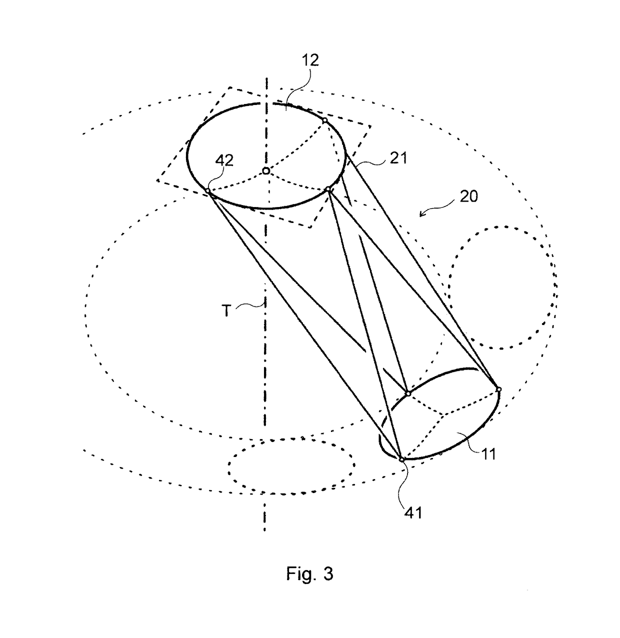
The invention is a structure, comprisinga first functional element (11) and a second functional element (12), said functional elements (11, 12) being form-retentive and being cooperatively functional in an operational state of the structure, in said operational state the functional elements (11, 12) having a predetermined relative spatial arrangement and being distanced from each other;a tension assembly (20) coupling the functional elements (11, 12) to each other, the tension assembly (20) being adapted to be taut in said operational state and being coupled to the first functional element (11) by respective first couplings and to the second functional element (12) by respective second couplings; the functional elements (11, 12), the couplings and the tension assembly (20) together forming a tensioned assembly; anda tensioning assembly (30) coupled to the tensioned assembly, the tensioning assembly (30) being adapted to exert a repulsive force distancing the first functional element (11) and the second functional element (12) for maintaining said operational state,wherein the system compliance of the tensioned assembly is less than 60% of the system compliance of the tensioning assembly (30).

Description

TECHNICAL FIELD[0001]The invention relates to a structure that offers the possibility to create construction systems for various purposes, especially for devices for the manipulation of electromagnetic waves. Relative spatial positioning of separate device elements or device subsystems of self-maintained shapes is achieved via tension components or tension subsystems between, and tension in the connecting tension elements or subsystems is maintained by substantially less stiff structures or structural elements.BACKGROUND ART[0002]Instruments and devices that interact with (sense, emit, filter, transform, receive, reflect, refract, actively process, interpret information embedded in, provide protection from, etc.) electromagnetic (EM) radiation energy and energy patterns are essential to modern technology. In space, such devices are the core equipment elements for a number of missions. Astronomical research, communication, remote sensing, and surveillance are just a few examples.[000...

Claims


Application Information

Patent Timeline
IPC IPC(8): H01Q1/28H01Q1/08H01Q3/01
CPCH01Q1/28H01Q3/01H01Q1/08B64G1/22B64G2001/224B64B1/08H01Q15/20H01Q15/161H01Q1/288H01Q1/1235H01Q19/18B64G1/2227
Inventor GRESCHIK, GYULA ISTVAN
Owner TENTGUILD ENG CO
Learn More