Apparatus and methods for activating a downhole percussion tool

a technology of percussion tools and apparatus, applied in mechanical apparatus, machines/engines, positive displacement liquid engines, etc., can solve the problems of tool collapse and create percussive force, and achieve the effect of avoiding impact loading on the cams

Inactive Publication Date: 2018-03-01
NAT OILWELL DHT
View PDF0 Cites 4 Cited by
  • Summary
  • Abstract
  • Description
  • Claims
  • Application Information

AI Technical Summary

Benefits of technology

[0005]Embodiments disclosed herein include a percussion tool employing a positive displacement pump having radially-arranged pistons which cooperate to cause percussion surfaces first to separate and then fall into contact. The pump includes a cam ring coupled to a tool housing. Pistons engage the cam ring and are pushed radially inward by the cam ring to pump fluid. The pumped fluid flows through a passage and acts on an actuation piston. The pressure created by the pump extends or lifts the tool, separating the percussion surfaces. Upon rotation of the piston's housing, a fluid port comes into alignment with an intake port. When this occurs, the fluid action on the actuation piston is released and the tool collapses and creates the percussive force. As the piston housing rotates further, the pistons extend and fluid is sucked into the piston cylinder, and the cycle repeats. This arrangement beneficially avoids impact loading on the cams. Further, multiple, axially-spaced stages of the pistons can be used to spread the load. Rolling contact between the piston and cam is possible.

Problems solved by technology

When this occurs, the fluid action on the actuation piston is released and the tool collapses and creates the percussive force.

Method used


Image

  • Apparatus and methods for activating a downhole percussion tool
  • Apparatus and methods for activating a downhole percussion tool
  • Apparatus and methods for activating a downhole percussion tool

Examples


Embodiment Construction

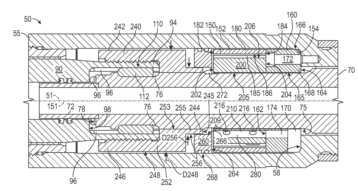
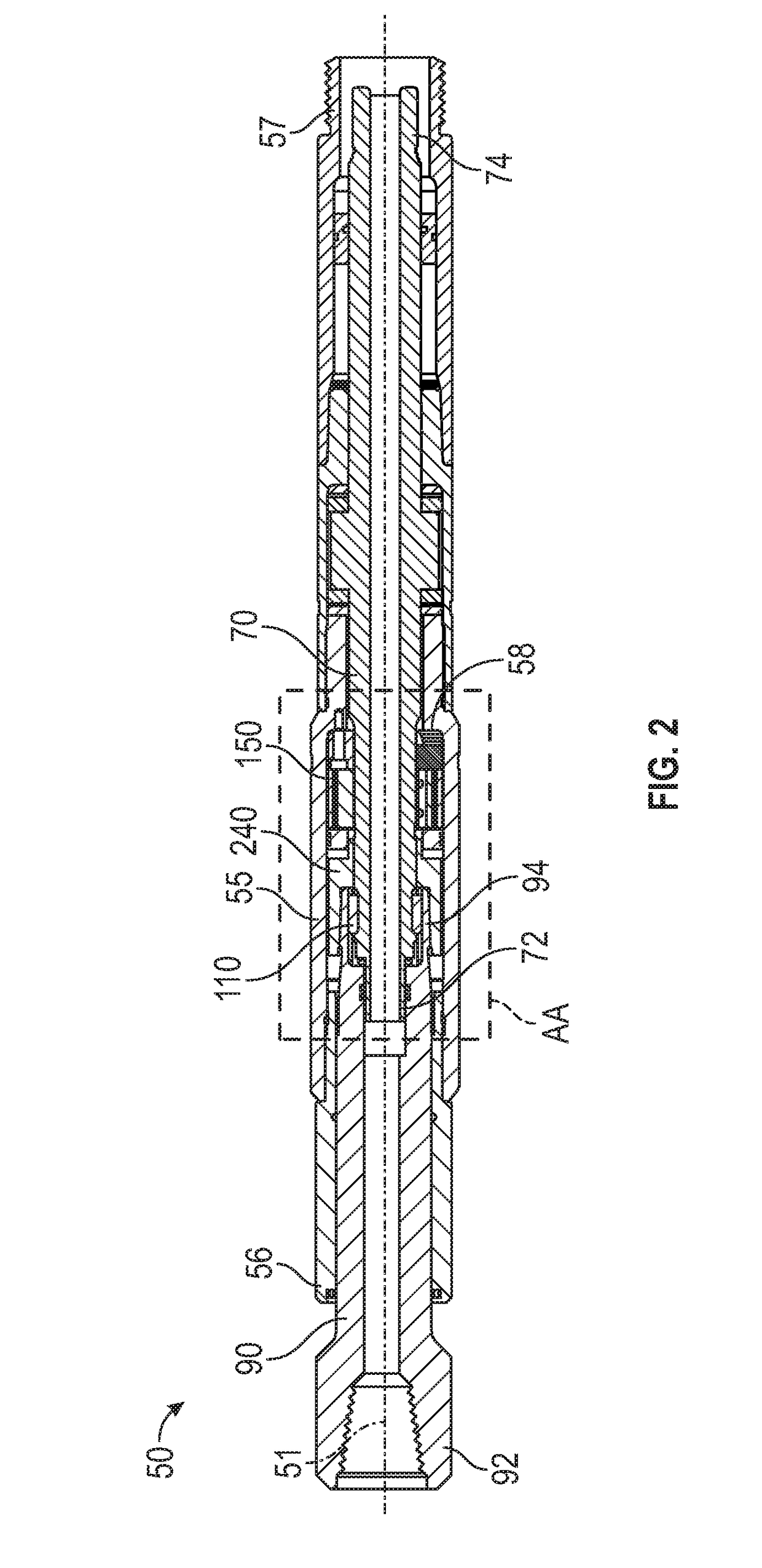
[0042]This disclosure describes a pump and a percussion tool which can be employed to create vibration and movement in a down hole tool to enhance the tool's rate of penetration through the formation.

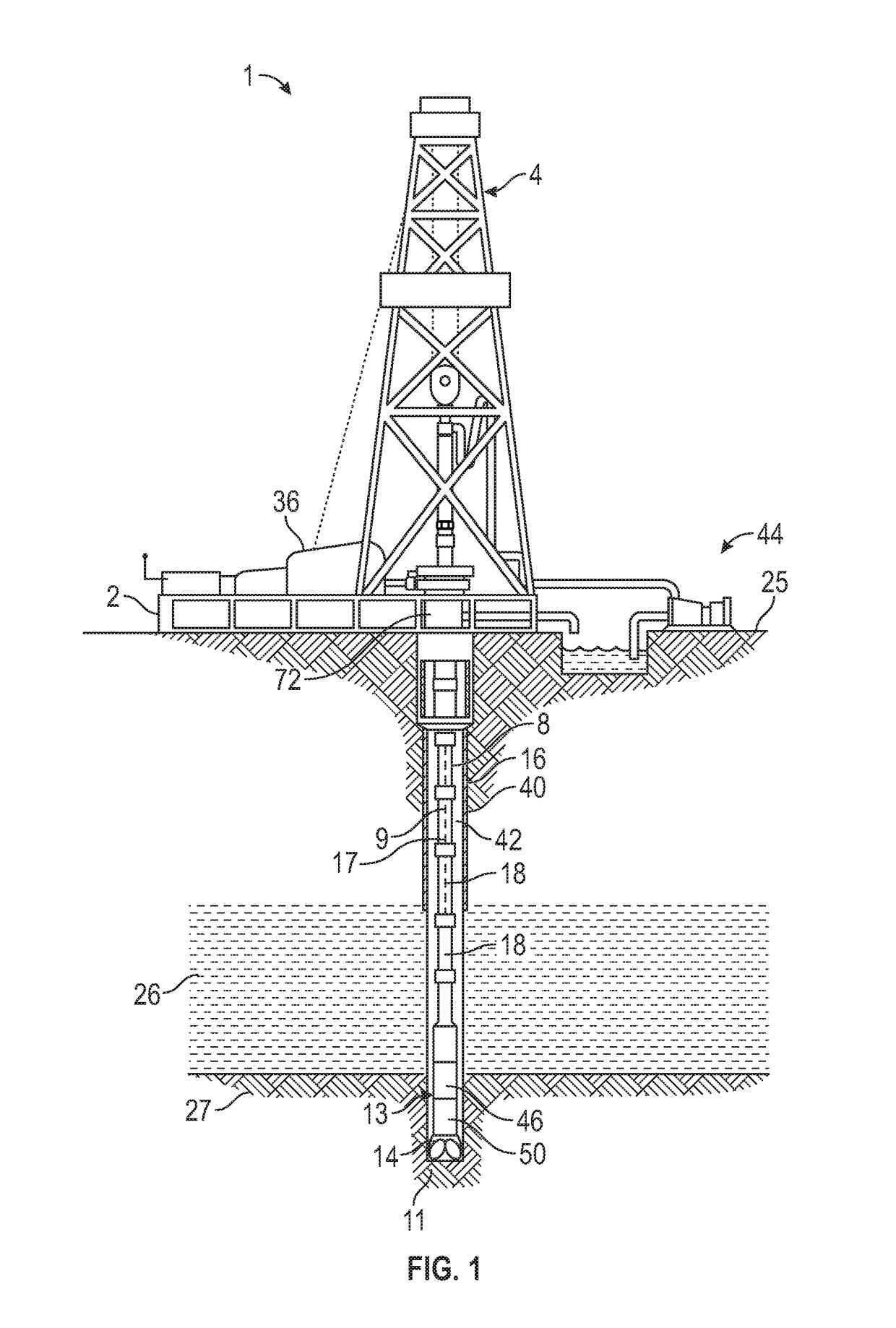
[0043]FIG. 1 is a schematic diagram showing an embodiment of a well system in accordance with principles described herein. Well system 1 includes a tubular string 8 (e.g., drill string, production tubing string, coiled tubing, etc.) to accomplish downhole operations. In the example shown, tubular string 8 is a drill string, and well system 1 is a drilling system that includes a derrick 4 supported by a drilling platform 2. Although FIG. 1 shows a land-based drilling system, the present disclosure is also applicable to off-shore well drilling systems.

[0044]The drill string 8 extends downward and comprises a longitudinal axis 9 and various components, including one or more tubular members 18 (i.e. pieces of drill pipe, which may also be called a pipe joint) coupled together end-to-end and...


PUM


Abstract

A percussion tool includes an actuating piston and a pump. The pump includes: a cam ring, a valve plate, a piston housing, and a piston. The cam ring includes an aperture having a camming surface. The valve plate faces the cam ring and includes a fluid port extending therethrough. The piston housing includes a fluid passage extending therethrough and is disposed within the aperture of the cam ring and rotates within the cam ring. A piston reciprocates within the piston housing. The fluid passage in the piston housing is configured to alternate between being in fluid communication with the fluid port in the valve plate and being isolated from the fluid port as the piston housing is rotated relative to the cam ring and valve plate. The flow port in the valve plate is larger in flow area than the flow area of the fluid passage in the piston housing.

Description

CROSS-REFERENCE TO RELATED APPLICATIONS[0001]This application claims benefit of U.S. provisional patent application Ser. No. 62 / 380,121 filed Aug. 26, 2016, and entitled “Apparatus and Methods for Activating a Downhole Percussion Tool,” which is hereby incorporated herein by reference in its entirety for all purposes.STATEMENT REGARDING FEDERALLY SPONSORED RESEARCH OR DEVELOPMENT[0002]Not applicable.BACKGROUND[0003]This disclosure relates generally to downhole tools and equipment used in the recovery of oil and gas. More particularly, it relates to an apparatus and a system to generate an impact force within a tool. Still more particularly, this disclosure relates to an impact-generating tool suitable for use in the bottom hole assembly of a tubular string deployed in an oil well, the tool configured to enhance the rate of penetration through the formation that is being drilled.[0004]While drilling a wellbore, percussion tools are sometimes employed to generate an axial motion of a ...

Claims


Application Information

Patent Timeline
Patent Type & Authority Applications(United States)
IPC IPC(8): E21B1/00F04B1/047F15B15/02F15B15/18
CPCE21B1/00F04B1/047F15B15/02F15B15/18E21B4/02F15B2215/30E21B4/14
Inventor TUTT, JOSHUA CALEB
Owner NAT OILWELL DHT
Why Eureka
Try Eureka