
Electronic parking brake

a technology electric motors, applied in the field of electric parking brakes, can solve the problems of reducing the operation response speed, affecting the operation efficiency of the braking system, so as to prevent the occurrence of bending deformation, improve power transmission performance, and prevent the effect of increasing the strok

Active Publication Date: 2018-03-01
HL MANDO CORP
View PDF43 Cites 3 Cited by
  • Summary
  • Abstract
  • Description
  • Claims
  • Application Information

AI Technical Summary

Benefits of technology

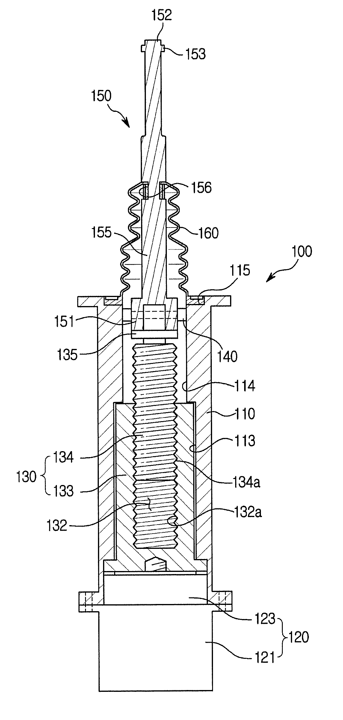
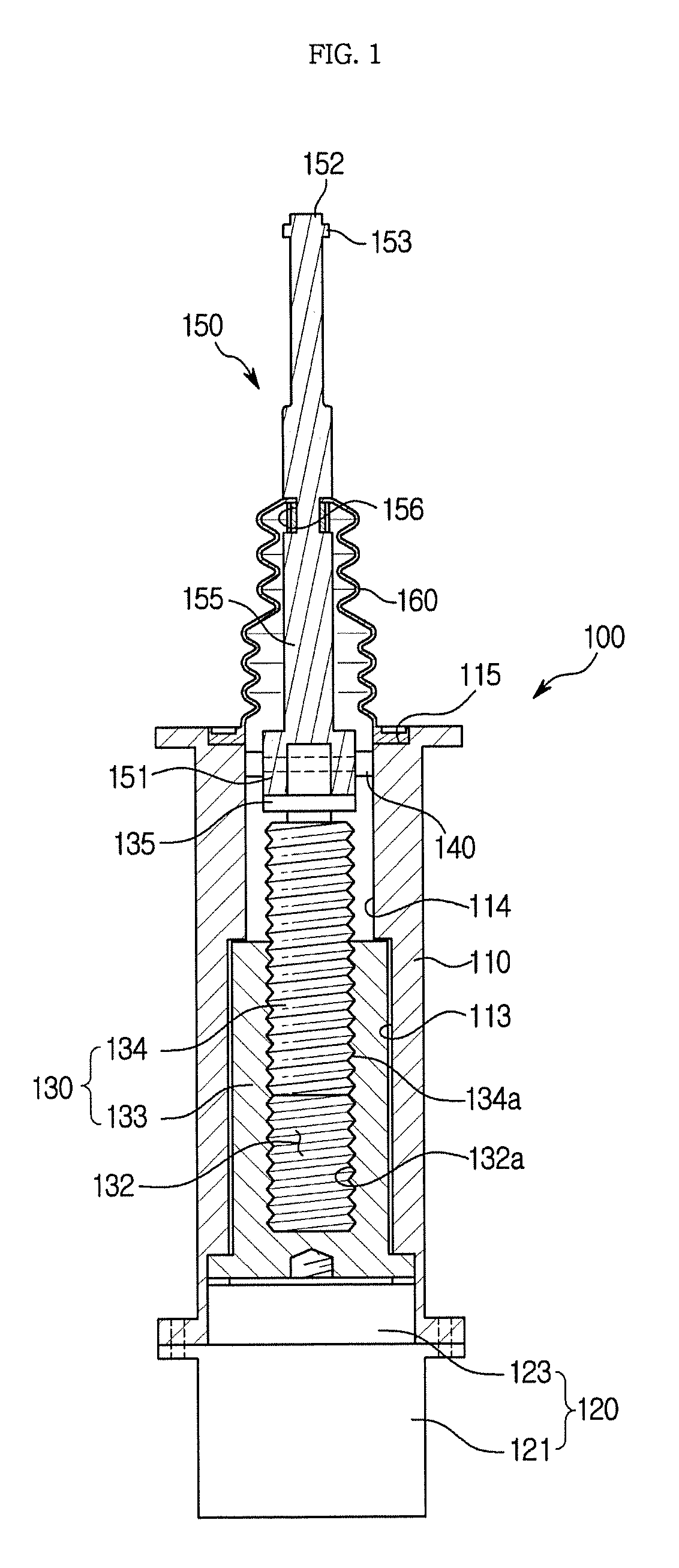
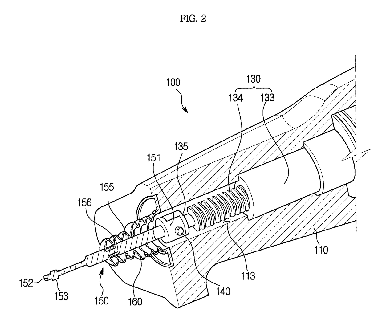
The present invention is directed to an electronic parking brake system that prevents an increase in braking operation and improves power transmission performance. It includes a parking cable with a single integrated type steel bar body to prevent bending deformation. The parking cable and a pivot lever are provided in surface contact with each other, resulting in improved durability during braking operation. A dual sealing structure prevents foreign materials and moisture from entering the housing. The brake system includes an operating lever to support brakes and a power conversion unit to generate a driving force for braking. The parking cable is connected to one side of a spindle member and has a predetermined length and a single integrated type steel bar body to prevent bending deformation. The brake system can also include a dust cover to prevent foreign materials from entering the power conversion unit.

Problems solved by technology

However, since the pivot lever and an end portion of the parking cable, which is connected to the pivot lever, are provided to be in one-side contact with each other, an operating load is concentrated on a portion that is in one-side contact such that a problem of damage to the pivot lever or the parking cable occurs.
Also, when a parking braking force is generated for a long time, a bending phenomenon occurs on a parking cable configured with a twisted wire such as a wire and the like, and thus there are problems in that a one-side contact occurs and a stroke section (a section from a braking generation time to a braking completion time) is increased such that an operation response speed is reduced.
In addition, since a known electronic parking brake is provided with a sealing structure employing a single dust cover, when a parking braking force is repetitively generated, a contact portion between the dust cover and the parking cable is worn by operational friction between the dust cover and the parking cable such that a problem in that moisture and foreign materials flow inside the housing occurs.
Consequently, due to the inflow of the foreign materials and the moisture, an abnormal load occurs at an electronic component and a mechanical component such that a failure occurs, and thus a problem of shortening the lifetime of a product occurs.

Method used


Image

  • Electronic parking brake
  • Electronic parking brake
  • Electronic parking brake

Examples


first embodiment

[0057]FIG. 6 is a diagram illustrating another configuration example of the parking cable and the pivot lever of the electronic parking brake according to the present disclosure, and FIG. 7 is a diagram illustrating a contact state between the parking cable and the pivot lever of FIG. 6. Here, the same reference numbers as those in the above-described drawings refer to members performing the same functions.

[0058]Referring to FIGS. 6 and 7, a latching part 153′ is formed to protrude from the second coupler 152 to be in surface contact with an upper side of each of a pair of supporters 172′ of the pivot lever 170′. The latching part 153′ has an outer surface with a rounded shape. Also, a surface of each of the pair of supporters 172′, which is in contact with the outer surface of the latching part 153′, is formed to have a rounded shape. Accordingly, the latching part 153′ and the pivot lever 170′ are provided in a state of being in smooth surface contact with each other.

[0059]Referri...

second embodiment

[0080]Also, the dust cover 360 is provided with first and second dust covers 361 and 365, and the first and second dust covers 361 and 365 have the same configurations and perform the same functions as the first dust cover 261 and the second dust cover 265 of the

[0081]The electronic parking brake 300 having the above-described structure will be briefly described.

[0082]The parking cable 350 is formed with a single integrated type steel bar body to prevent occurrence of a bending deformation. That is, the parking cable 350 is provided with a first coupler 351 coupled to a spindle member 334, a second coupler 352 coupled to a pivot lever (not shown), and a connector 355 configured to connect the first coupler 351 to the second coupler 352. Here, a latching part 353 is formed to protrude from the second coupler 352 and is connected to the pivot lever to operate the pivot lever. An outer surface of the latching part 353 may be configured to have a rounded shape, and thus the latching par...


PUM


Abstract

Disclosed is an electronic parking brake. The electronic parking brake is provided with an operating lever, which is configured to support first and second brake shoes, which are installed at both sides inside a drum, and push the first and second brake shoes toward an inner surface of the drum when a pivot lever is pulled, and is electronically activated to operate the pivot lever to brake the drum, and the electronic parking brake includes a housing mounted on a vehicle body; an actuator installed at the housing and configured to generate a driving force for braking; a power conversion unit having a nut member configured to be rotated by receiving the driving force from the actuator, and a spindle member screw-coupled to the nut member to allow a rectilinear movement; and a parking cable configured to move according to a reciprocal linear movement of the spindle member, operate the parking brake, release an operation of the parking brake, and be connected to an end of one side of the spindle member, wherein the parking cable has a predetermined length and is formed with a single integrated type steel bar body to prevent occurrence of a bending deformation.

Description

[0001]This application claims the benefit of Korean Patent Application Nos. 2016-0166549 and 2016-0111985, filed on Aug. 31, and Dec. 8, 2016, respectively in the Korean Intellectual Property Office, the disclosure of which is incorporated herein by reference.BACKGROUND1. Field[0002]Embodiments of the present disclosure relate to a parking brake mounted on a vehicle, and more particularly, to an electronic parking brake which is operated by a motor.2. Description of the Related Art[0003]Generally, a parking brake is a device for stopping a vehicle to prevent movement of the vehicle when the vehicle is parked, and serves to hold a wheel of the vehicle to prevent rotation of the wheel. For example, a parking brake is used as a drum in hat (DIH) type brake device, and conventionally, the parking brake pulls a parking cable according to a manipulation of a hand brake or a foot brake to generate a braking force. At this point, when a drum brake is used as the parking brake, the DIH type ...

Claims


Application Information

Patent Timeline
Patent Type & Authority Applications(United States)
IPC IPC(8): F16D65/28B60T7/10
CPCF16D65/28B60T7/107F16D51/00F16D2121/24F16D2125/40F16D2125/62F16D2125/64F16D65/005F16D65/14F16J3/041F16D2121/18B60T13/746F16D51/22F16D51/28F16D2125/60
Inventor LEE, HYON-JANGJUNG, YOO-DONSON, MOO-KANG
Owner HL MANDO CORP
Learn More