
Non-metallic high pressure high temperature high chemical compatibility flange isolation gasket

a flange isolation and high temperature technology, applied in the direction of flanged joints, other domestic objects, mechanical equipment, etc., can solve the problems of posing a substantial risk to human life, and limiting the width of currently available sealing elements

Active Publication Date: 2018-03-01
ROWLEY MARC +1
View PDF29 Cites 12 Cited by
  • Summary
  • Abstract
  • Description
  • Claims
  • Application Information

AI Technical Summary

Benefits of technology

The patent text describes a non-metallic flange isolation gasket kit that provides high-pressure, high-temperature, and high-chemical compatibility with increased electrical isolation properties. The kit includes a retainer, a seal, and a seal pre-load structural ring. The retainer is made from reinforced resin material, while the seal pre-load structural ring is made from a specialized material called a convolute. The kit also has tapered surfaces that help decrease flange rotation. Overall, this non-metallic flange isolation gasket kit is designed to provide superior performance and reliability in high-pressure, high-temperature, and high-chemical environments.

Problems solved by technology

In some cases, these fluids and gases are explosive and / or have toxic properties that can pose a substantial risk to human life in case of leaks.
A number of factors also limit the width of currently available seal elements.
These size and volume constraints prevent currently available sealing elements to have the mechanical properties necessary to sustain high pressures over long periods of time.
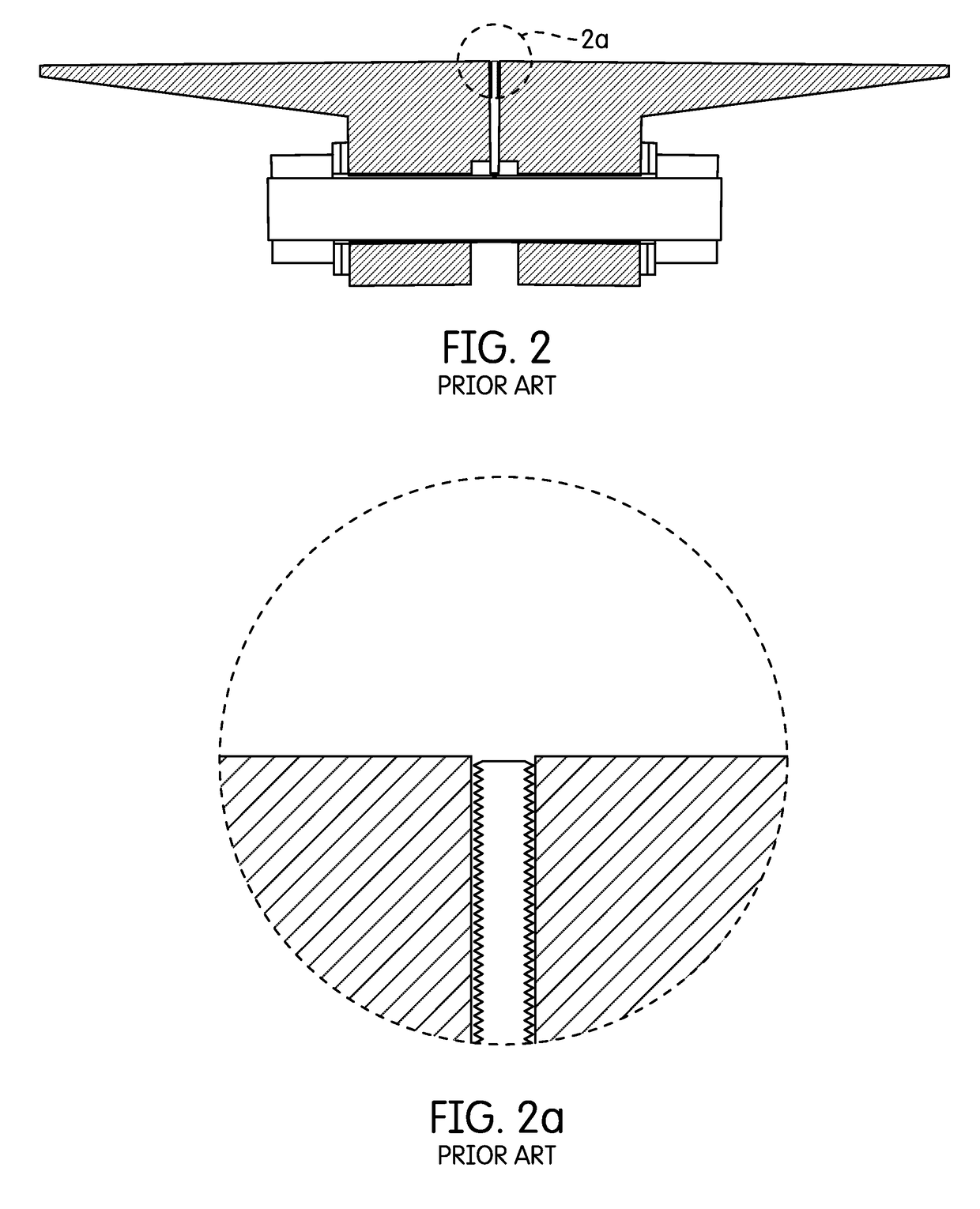
Retainers made from a metal core have numerous weaknesses.
The presence of a metal core at the inner diameter of the retainer compromises electrical isolation between flange connectors.
The laminate layer is approximately 0.090″ thick or less, providing limited isolation properties between flange faces; fluids flowing through the pipeline can easily bridge this gap, limiting the efficiency of a cathodic protection system with a flange isolation kit.
This three-layer composition creates significant manufacturing process variation stack-up that compromises seal efficiency in flange isolation gaskets; this large manufacturing process variation stack-up leads to non-uniform retainer thickness.
This thin metal core can become a failure point.
In opposed-face-seal design retainers, if the three-layer composition thickness is too thick, the sealing element grooves will be very shallow in the metal core; the metal core will not provide support for the sealing elements.
Since the plastic laminate only has bi-directional strength, it cannot support the sealing elements in high pressure / high temperature applications.
For inner diameter seals, if the three-layer composition thickness is too thick, the sealing element will not be compressed enough to function properly.
The flow of corrosive fluids through the pipeline degrades the flange face, reducing flange life expectancy.
An inner diameter seal can be over-compressed, causing seal extrusion and spring damage.
An inner diameter seal can be under-compressed, compromising performance drastically.
Deteriorated seal compression increases susceptibility to explosive decompression.
Explosive decompression is the uncontrolled depressurization of a fluid in pipelines utilizing flange isolation kits due to material failure in components such as gaskets and piping.
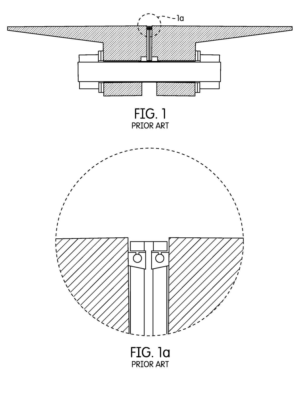
There are a number of weaknesses in flange isolation gaskets made from a Kammprofile gasket design.
The presence of a metal core at the inner diameter of the retainer compromises electrical isolation between flange connectors.
The dielectric thin film is even thinner than 0.090″, providing very limited electrical isolation; fluids flowing through the pipeline can easily bridge this gap, limiting the efficiency of an installed cathodic protection system.
At operating pressures, the compressive force exerted on the thin dielectric layer weakens it.
In summary, currently available high-pressure flange isolation gaskets have many design weaknesses: 1) the use of metal compromises dielectric properties, 2) the presence of multiple inboard sealing elements increases failure points and reduces flange life expectancy, and 3) the exposure of multiple materials to highly corrosive media requires numerous combinations to handle different applications.
This flange rotation causes flange faces to lift off the sealing elements, potentially beyond the minimum seal seating load, causing poor sealing or seal failure.
As the flange faces lift off the sealing elements, internal pressure can extrude the sealing elements past the retainer and cause seal damage or premature seal failure.
The bond strength in a three-layer composition structure may not be homogeneous throughout the retainer surface, providing a weak / failure point in high pressure / high temperature applications for currently available design flange isolation gaskets.

Method used


Image

  • Non-metallic high pressure high temperature high chemical compatibility flange isolation gasket
  • Non-metallic high pressure high temperature high chemical compatibility flange isolation gasket
  • Non-metallic high pressure high temperature high chemical compatibility flange isolation gasket

Examples


first embodiment

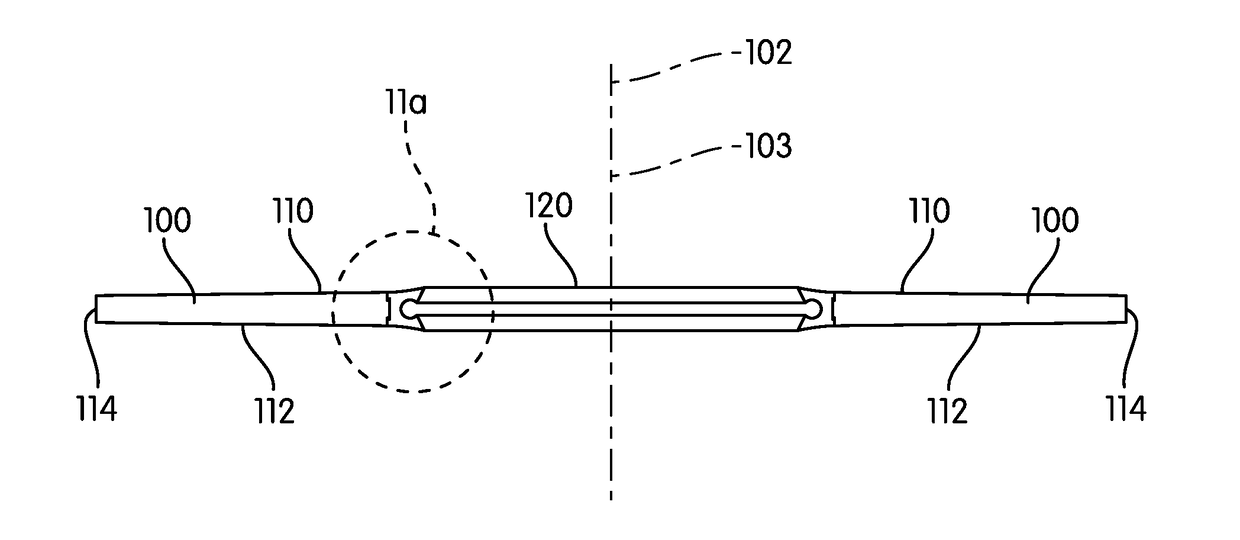
[0079]the non-metallic flange isolation gasket kit comprises of a retainer (100), a seal (120), and a seal pre-load structural ring (140). The retainer (100) is precision machined from a reinforced resin material that provides high pressure, high temperature, and high chemical compatibility with increased electrical isolation properties. For example, the retainer may be precision machined from washer-shaped slices of cured filament wound material (91) or cured convolute wrapped pre-preg material (92). The seal pre-load structural ring (140) is inserted into the seal (120), and the seal outer diameter surface (122) is joined to the retainer inner diameter surface (116). Flange rotation is decreased by having the upper and lower surfaces of the retainer (100) be tapered.

second embodiment

[0080]the non-metallic flange isolation gasket kit comprises of a composite gasket blank (160) and a seal pre-load structural ring (140). The composite gasket blank (160) comprises of a retainer (100) and a seal (120). The composite gasket blank (160) is made through a composite winding / wrapping process, where tube shape compression molded fluoropolymer (350) is over molded with one or more layers of impregnated composite fiber filaments (303) and one or more layers of semi-cured impregnated composite fabric matrix (326). This material is then cured and cut. The seal (120) is machined from the tube shape compression molded fluoropolymer (350) section of the composite gasket blank (160). The retainer (100) is machined from the cured filament wound material (91) and cured convolute wrapped pre-preg material (92) section of the composite gasket blank (160). The seal outer diameter surface (122) and the retainer inner diameter surface (116) are joined by thermal fusion bonding.

[0081]The...


PUM

PropertyMeasurementUnit
temperatureaaaaaaaaaa
operating temperaturesaaaaaaaaaa

Abstract

A non-metallic flange isolation gasket kit sealing flanged pipeline connections and flanged vessel connections while providing electrical isolation protection between flanges suited for high-pressure and high-temperature cathodic protection applications is presented. The invention protects flange faces from media induced corrosion and mitigates flange rotation induced fatigue and failures. The invention comprises of a retainer, a seal, and a seal pre-load structural ring. The seal pre-load structural ring is inserted into the seal, and seal outer diameter surface is joined to the retainer inner diameter surface. A second embodiment comprises of a composite gasket blank, comprising of a retainer and a seal, and a seal pre-load structural ring. The seal outer diameter surface and the retainer inner diameter surface are joined by thermal fusion bonding. The invention may further comprise one or more gasket seating stress stabilizers and / or a centering ring. Tapered retainer upper and lower surfaces decrease flange rotation.

Description

CROSS-REFERENCE TO RELATED APPLICATIONS[0001]This application claims the priority benefit of U.S. Provisional Patent Application Ser. No. 62 / 379,383 filed Aug. 25, 2016.STATEMENT REGARDING FEDERALLY SPONSORED RESEARCH OR DEVELOPMENT[0002]Not ApplicableTHE NAMES OF THE PARTIES TO A JOINT RESEARCH AGREEMENT[0003]Not ApplicableREFERENCE TO A “SEQUENCE LISTING,” A TABLE, OR A COMPUTER[0004]Not ApplicableBACKGROUND OF THE INVENTION(1) Field of Invention[0005]A non-metallic flange isolation gasket kit that seals flanged pipeline connections and flanged vessel connections while providing electrical isolation protection between flanges is presented. The non-metallic flange isolation gasket kit can be used in high pressure and high temperature cathodic protection applications without the need for metal components. The non-metallic flange isolation gasket kit protects flange faces from media induced corrosion and mitigates flange rotation induced fatigue and failures.(2) Description of Relate...

Claims


Application Information

Patent Timeline
Patent Type & Authority Applications(United States)
IPC IPC(8): F16L23/22F16J15/10F16J15/06B29C70/32B29C70/68B29C70/74
CPCF16L23/22F16J15/108F16J15/064F16J15/102B29C70/32B29C70/683B29C70/74B29L2031/265B29K2627/18B29K2063/00B29C70/545F16J15/104F16L25/026F16L23/18
Inventor ROWLEY, MARCRUZ, SIGFRID
Owner ROWLEY MARC
Learn More