

Polarizing plate and image display device comprising the same
a technology of polarizing plates and image displays, applied in the direction of polarising elements, instruments, applications, etc., can solve the problem of insufficient folding characteristics of flexible displays, and achieve the effect of excellent bending resistance and effective us
- Summary
- Abstract
- Description
- Claims
- Application Information
AI Technical Summary
Benefits of technology
Problems solved by technology
Method used
Image

Examples
preparation example 1
Preparation of Composition for Forming Polarizing Coating Layer
[0137]100 parts by weight of a compound represented by the following formula as a polymerizable liquid crystal compound, 2 parts by weight of an azo dye (NKX2029; Hayashibara Seibutsu Kagaku Kenkyujo), 6 parts by weight of 2-dimethylamino-2-benzyl-1-(4-morpholinophenyl)butan-1-one as a polymerization initiator (Irgacure 369; BASF Japan Ltd.), 2 parts by weight of isopropylthioxanthone as a photosensitizer (Nippon Siber Hegner), 1.2 parts by weight of polyacrylate compound as a leveling agent (BYK-361N; BYK-Chemie) and 250 parts by weight of cyclopentanone as a solvent were mixed, and the thus-obtained mixture was stirred at 80° C. for 1 hour to prepare a composition for forming a polarizing coating layer.
preparation example 2
Preparation of Composition for Forming Retardation Coating Layer
[0138]A composition for forming a retardation coating layer was prepared in the same manner as in Preparation Example 1, except that the azo dye was not included.
preparation example 3
Preparation of Composition for Forming a Soft Layer
[0139]A composition for forming a soft layer was prepared by mixing each component in the composition shown in Table 1 below (unit: parts by weight).
TABLE 1PreparationPreparationPreparationPreparationPreparationExampleExampleExampleExampleExample3-13-23-33-43-5122P51020400SC2565353020040Photoinitiator2.52.52.52.52.5Leveling0.50.50.50.50.5AgentSolvent6060606060122P: Bifunctional urethane acrylate oligomer (Shin Nakamura Chemical)SC2565: Bifunctional urethane acrylate oligomer (Miwon Co., Ltd)Photoinitiator: Irg-184 (BASF Corporation)Leveling Agent: BYK-3570 (BYK-Chemie)Solvent: Methyl ethyl ketone (MEK)
PUM
| Property | Measurement | Unit |
|---|---|---|
| total thickness | aaaaa | aaaaa |
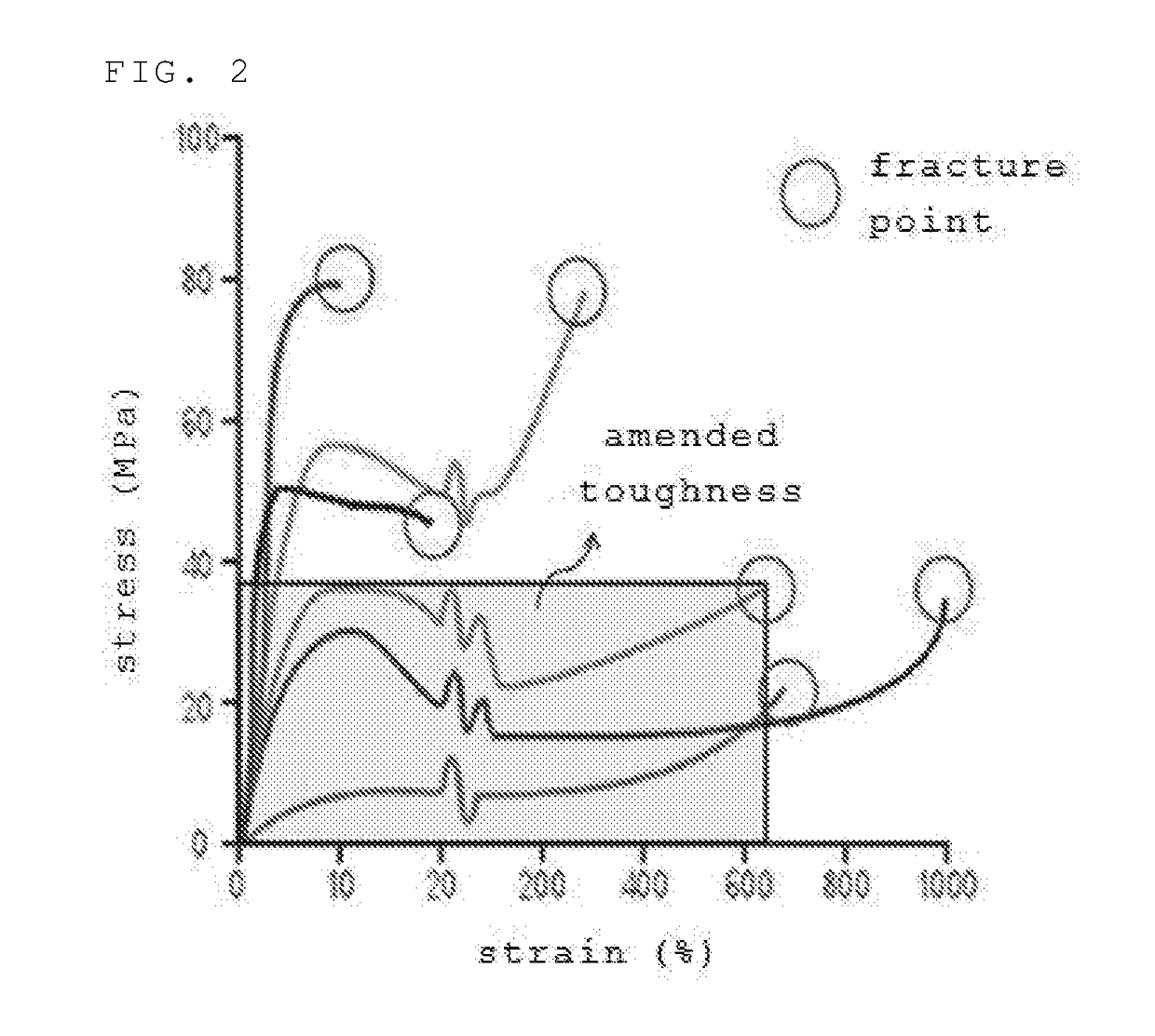
| toughness | aaaaa | aaaaa |
| stress×maximum strain | aaaaa | aaaaa |
Abstract
Description
Claims
Application Information