System and method for retaining memory modules

a memory module and memory technology, applied in the field of system and method for retaining memory modules, can solve the problems of affecting the operation of the joint electron device engineering council, the failure of the dimm and the motherboard to be able to operate normally, and the loss of electrical connectivity between the spring contact and the circuit card, so as to reduce the inadvertent disconnection of memory modules and further deter the rotation of the connector latch

Active Publication Date: 2018-03-01
CRYSTAL GROUP
View PDF34 Cites 27 Cited by
  • Summary
  • Abstract
  • Description
  • Claims
  • Application Information

AI Technical Summary

Benefits of technology

[0008]It is an advantage of the present invention to reduce inadvertent disconnection of memory modules from a DIMM connector.
[0009]It is another feature of the present invention to include a bumper spacer between adjacent retention clips.
[0010]It is another advantage of the present invention to provide a self-alignment capability for a plurality of adjacent retention clips.
[0011]It is yet another feature of the present invention to have a tab on the ends of clip.
[0012]It is still another advantage of the present invention to further deter rotation of a connector latch.
[0013]It is still another feature to have a lid contacting surface on the retention clip.

Problems solved by technology

One of several obstacles requiring resolution is the fragility of the Joint Electron Device Engineering Council (JEDEC) style DIMM connector on these compute platforms.
More frequently, the spring contact and the circuit card lose electrical connectivity when the chassis is distorted.
This level of chassis deflection creates enough force to curve the motherboard, which drives the JEDEC latch up and the DIMM out of the connector, thereby creating a break in the electrical connectivity between the DIMM and the motherboard.
The latch, which is designed to both retain the memory as well as extract the memory, is prone to creating a problem in shock and vibration.
This is a particularly devastating event for these system architectures as they fail to operate normally thereafter until the connection is reestablished.
Previous solutions have involved permanently bonding the DIMM into the connector of applying a retention band, which must be damaged on removal.
The former is unserviceable while the latter requires depot repair.

Method used


Image

  • System and method for retaining memory modules
  • System and method for retaining memory modules
  • System and method for retaining memory modules

Examples


Embodiment Construction

[0050]Through this description details are given of a DIMM and a DIMM connector, it should be understood that different circuit cards with different types of electronic components could be used with different connector sizes and configurations. It is intended that these specific details not limit the scope of the present invention but instead fully enable a one specific and best mode of the invention and other variations of this card and connector types are intended to be readily understood from the following description and included within the scope and spirit of the present invention.

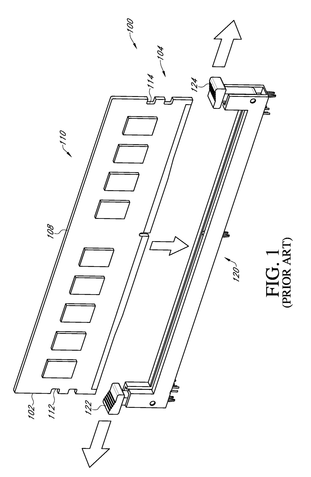
[0051]Now referring to the drawings wherein like numerals refer to like matter throughout, and more specifically referring to FIG. 1, there is shown a system of the prior art, generally designated 100, including a prior art DIMM and connector 100 including a DIMM memory module 110 and a DIMM connector 120. DIMM memory module 110 has a first end 102, a second end 104, a first end card notch 112 which p...


PUM


Abstract

The present invention is an apparatus and method for allowing for the use of commercial dual inline memory module (DIMM) in high shock and vibration environments while preserving serviceability. This system extends the performance of the standard Joint Electron Device Engineering (JEDEC) memory connectors in said environments without sacrificing high speed electrical performance. The system provides a simple clip which locks the module in place using the standard connector latches preventing relative motion of the connector and the DIMM thereby insuring uninterrupted computational performance.

Description

CROSS REFERENCE TO RELATED APPLICATIONS[0001]This application claims the benefit of the filing date of the provisional patent application having Ser. No. 62 / 381,939 filed Aug. 31, 2016, the contents of which is incorporated herein in its entirety by this reference.FIELD OF THE INVENTION[0002]The present invention generally relates to computers and electronic equipment, and more particularly relates to industrial and military computers, and even more particularly relates to methods and systems for providing rugged DIMM connections for use in demanding and hostile environmentsBACKGROUND OF THE INVENTION[0003]Server class compute platforms are typically not employed in environments that are harsh, such as military vehicles, construction vehicles, weapons platforms, space launch systems, and etc. These server platforms are becoming necessary because of the need for virtualization and compute density in smaller spaces. One of several obstacles requiring resolution is the fragility of the...

Claims


Application Information

Patent Timeline
Patent Type & Authority Applications(United States)
IPC IPC(8): H01R12/70H01R12/73
CPCH01R12/7029H01R12/737H01R13/639
Inventor SHAW, JAMES E.MANSON, RACHELMARSDEN, CHASEGRAHAM, ROBERTSIEVERS, BRENTCASTILLO, SHAWN
Owner CRYSTAL GROUP
Why Eureka
Try Eureka