Wireless Connector Transmitter Module

a transmitter module and wired connector technology, applied in the direction of electrical apparatus casings/cabinets/drawers, casings/cabinets/drawers, coupling device connections, etc., can solve the problems of preventing proper function, affecting the microscopic connection area, and wired connectors typically do not allow relative motion between males, so as to reduce replace or eliminate the need for wired connectors, and improve the reliability and robust link

Active Publication Date: 2018-03-01
NUCURRENT INC
View PDF47 Cites 17 Cited by
  • Summary
  • Abstract
  • Description
  • Claims
  • Application Information

AI Technical Summary

Benefits of technology

[0019]Thus, provided is an electrical connector having a form factor that can replace or eliminate the need for wired connectors.
[0020]The wireless connector system of the present application provides a wireless power link that eliminates the need for a physical connection such as an electrical connector that physically joins two components together. Thus, by eliminating the physical connection, the wireless connector or power link can be completely encapsulated, preventing liquids and other debris ...

Problems solved by technology

This microscopic connecting area may become affected by different factors, such as harsh environments, vibration as well as wear and tear over time under normal operating conditions.
Furthermore, these traditional mechanical connectors generally require physical contact at a precise alignment to function properly.
Furthermore, wired connectors typically do not allow any relative motion between the male and the female portions.
Over time, due to this physical contact, these mechanical connection points typically experience forces that can fatigue and damage the pin or port, thereby preventing proper functionality.
Such prior art connectors may wear, flex, or may become corroded or damaged.
As a result, the physical connection between the corresponding male and female portions such as a pin and respective port may become compromised, thereby resulting in a loss of data or electrical energy transfer therebetween due to an impaired or inoperable connector.
Contamination, moisture and liquid ingress in a consumer, medical, military or industrial environment may pose undesirable prob...

Method used


Image

  • Wireless Connector Transmitter Module
  • Wireless Connector Transmitter Module
  • Wireless Connector Transmitter Module

Examples


Embodiment Construction

[0042]In the following description, numerous specific details are set forth by way of examples in order to provide a thorough understanding of the relevant teachings. However, it should be apparent to those skilled in the art that the present teachings may be practiced without such details. In other instances, well known methods, procedures, components, and / or circuitry have been described at a relatively high-level, without detail, in order to avoid unnecessarily obscuring aspects of the present teachings.

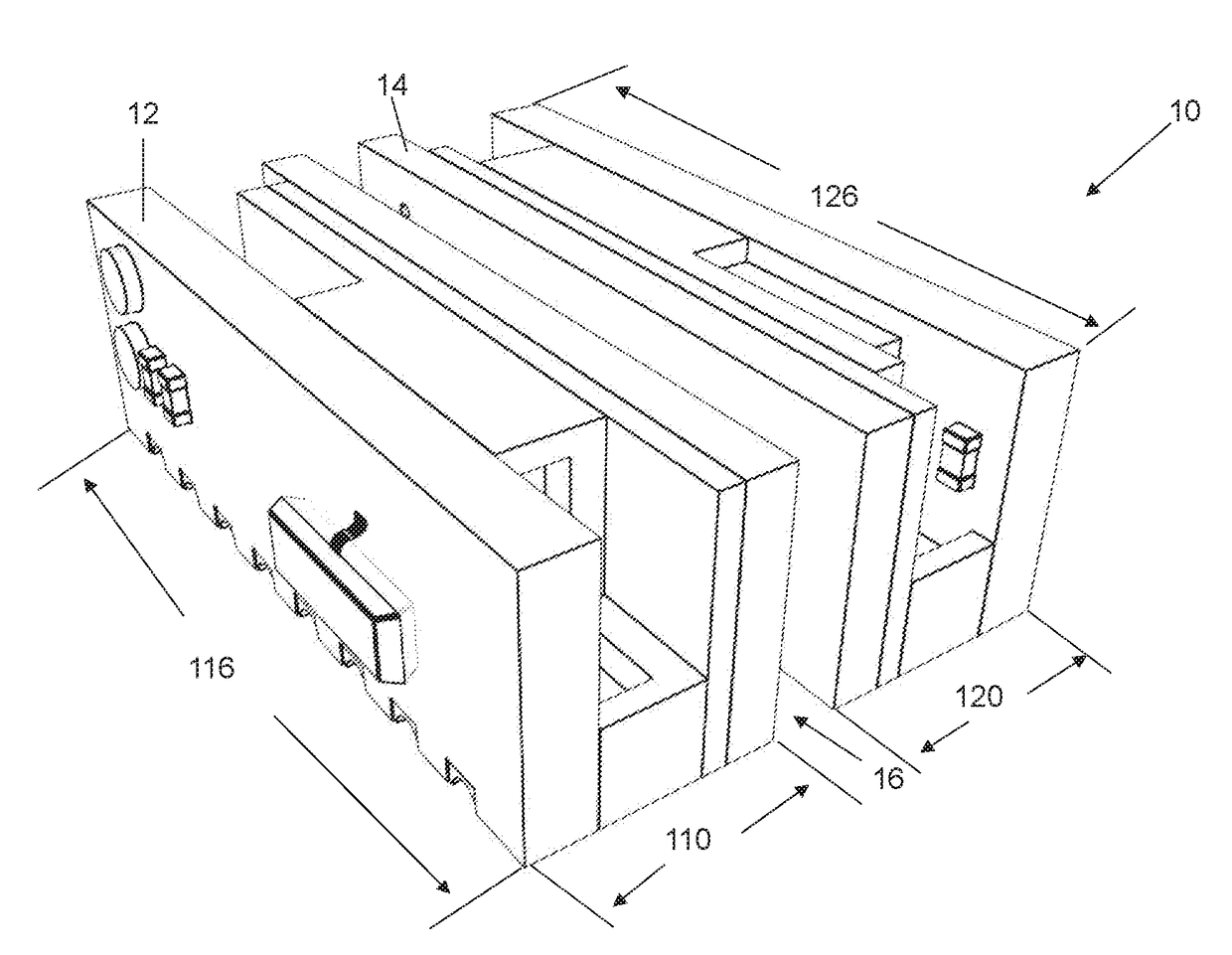
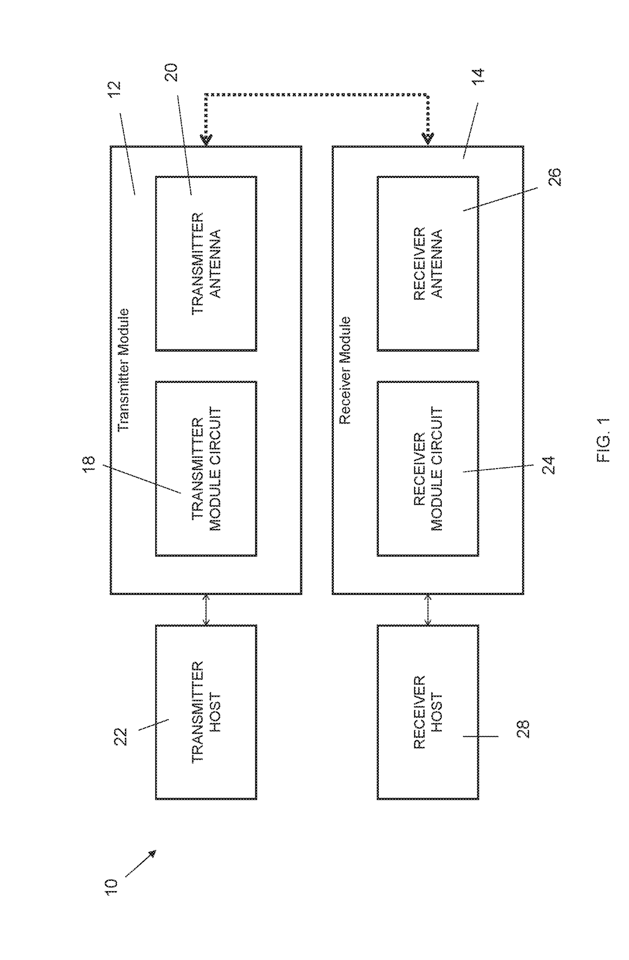
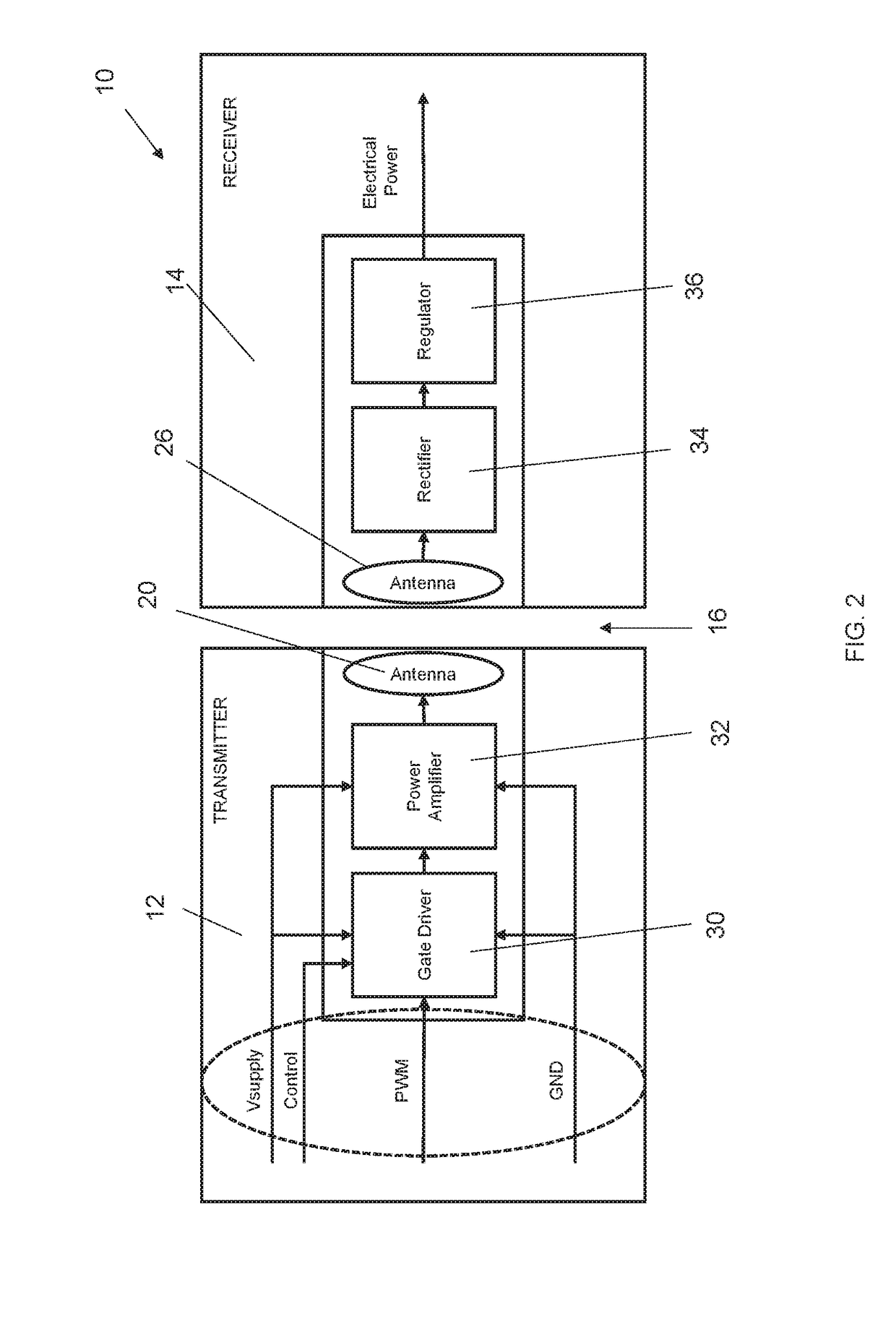
[0043]The wireless connector system 10 of the present disclosure provides for the wireless transfer of electrical energy and / or data. More specifically, the wireless connector system 10 of the present invention provides for the wireless transfer of electrical energy and / or data via near field magnetic coupling. In an embodiment, the wireless connector system 10 comprises a transmitter module 12 configured to transmit electrical energy and a receiver module 14 configured to receive...


PUM


Abstract

Various embodiments of a wireless connector system are described. The system has a transmitter module and a receiver module that are configured to wirelessly transmit electrical energy and/or data via near field magnetic coupling. The wireless connector system is designed to increase the amount of wirelessly transmitted electrical power over a greater separation distance. The system is configured with various sensing circuits that alert the system to the presence of the receiver module to begin transfer of electrical power as well as undesirable objects and increased temperature that could interfere with the operation of the system. The wireless connector system is a relatively small foot print that is designed to be surface mounted.

Description

RELATED APPLICATION[0001]This application claims priority to U.S. Provisional Application No. 62 / 379,940, filed on Aug. 26, 2016, the disclosure of which is entirely incorporated herein by reference.TECHNICAL FIELD[0002]The present disclosure generally relates to the wireless transmission of electrical energy and data. More specifically, this application relates to an electrical device that facilitates the wireless transmission electrical energy at multiple operating frequencies and frequency bands.BACKGROUND[0003]Prior art electrical connectors are traditionally constructed with a plurality of pins that physically plug into a corresponding receiving port. Each half of these connectors are typically assigned a male and a female designation which are subsequently mated to form an electrical contact.[0004]Fundamentally, an electrical connector is an electro-mechanical device comprising electrical conductors that are used to electrically and mechanically join other conductors, electric...

Claims


Application Information

Patent Timeline
IPC IPC(8): H04B5/00H02J50/10H03H11/28H02J50/60H05K9/00H05K5/02H01R12/70H01Q1/38H01Q1/52
CPCH04B5/005H01R12/7088H03H11/28H02J50/60H05K9/0084H05K5/0247H01R12/7082H01Q1/38H01Q1/526H04B5/0037H05K9/0022H01R12/724H01R12/725H01R12/721H01R12/732H02J50/10H03H7/38H05K9/0075H01Q7/00H05K1/0216H01R12/52H04B5/0075H01R12/57H04B5/0081H05K1/181H05K3/361H05K9/0081H01F38/14H04B1/04H04B5/0031H05K3/40H04B1/16H05K1/147H05K3/366H01Q1/42H05K1/148H05K1/028H05K2201/10098H02J50/005
Inventor SINGH, VINITSHOSTAK, PAVELPERALTA, ALBERTOLUZINSKI, JASONBABCOCK, JACOB D.GOTLIEB, MICHAELRIESE, GLENN E.ALAM, MD. NAZMULGIOMETTI, ROBERTLOSS, OLEG
Owner NUCURRENT INC
Why Eureka
Try Eureka