
Conduction-path-equipped member, method for patterning conduction path, and method for measuring changes in member

Inactive Publication Date: 2018-03-08
NEJILAW
View PDF43 Cites 51 Cited by
  • Summary
  • Abstract
  • Description
  • Claims
  • Application Information

AI Technical Summary

Benefits of technology

The patent text describes a way to verify changes in members or the environment surrounding them in a cost-effective way. This allows for the monitoring of a wide range of objects through mass production. The invention can also be applied to different types of members and in large quantities at a low cost.

Problems solved by technology

However, now there are an enormous number of constructions.
It is practically impossible to determine a structural material to be intensively maintained in one of the constructions while putting a priority on a construction material for which maintenance is to be performed.
Thus, the results are different from person to person and lack objectivity, and thus may not be used to determine radical maintenance.
Thus, it is difficult to prevent an accident or a financial loss resulting therefrom.
However, this method may not distinguish between an extension of the adhesive and an extension of the measurement target object.
Since the measurement target object may deteriorate or be peeled off due to temperature or humidity, a thermal effect, a different coefficient of thermal expansion, a fatigue strength by repeated expansions and contractions, or an issue of weather resistance or durability, it is essentially impossible to obtain a result of measuring an exact stress applied to the measurement target object.

Method used


Image

  • Conduction-path-equipped member, method for patterning conduction path, and method for measuring changes in member
  • Conduction-path-equipped member, method for patterning conduction path, and method for measuring changes in member
  • Conduction-path-equipped member, method for patterning conduction path, and method for measuring changes in member

Examples


Embodiment Construction

[0082]Hereinafter, embodiments of the present invention will be described in detail with reference to the accompanying drawings.

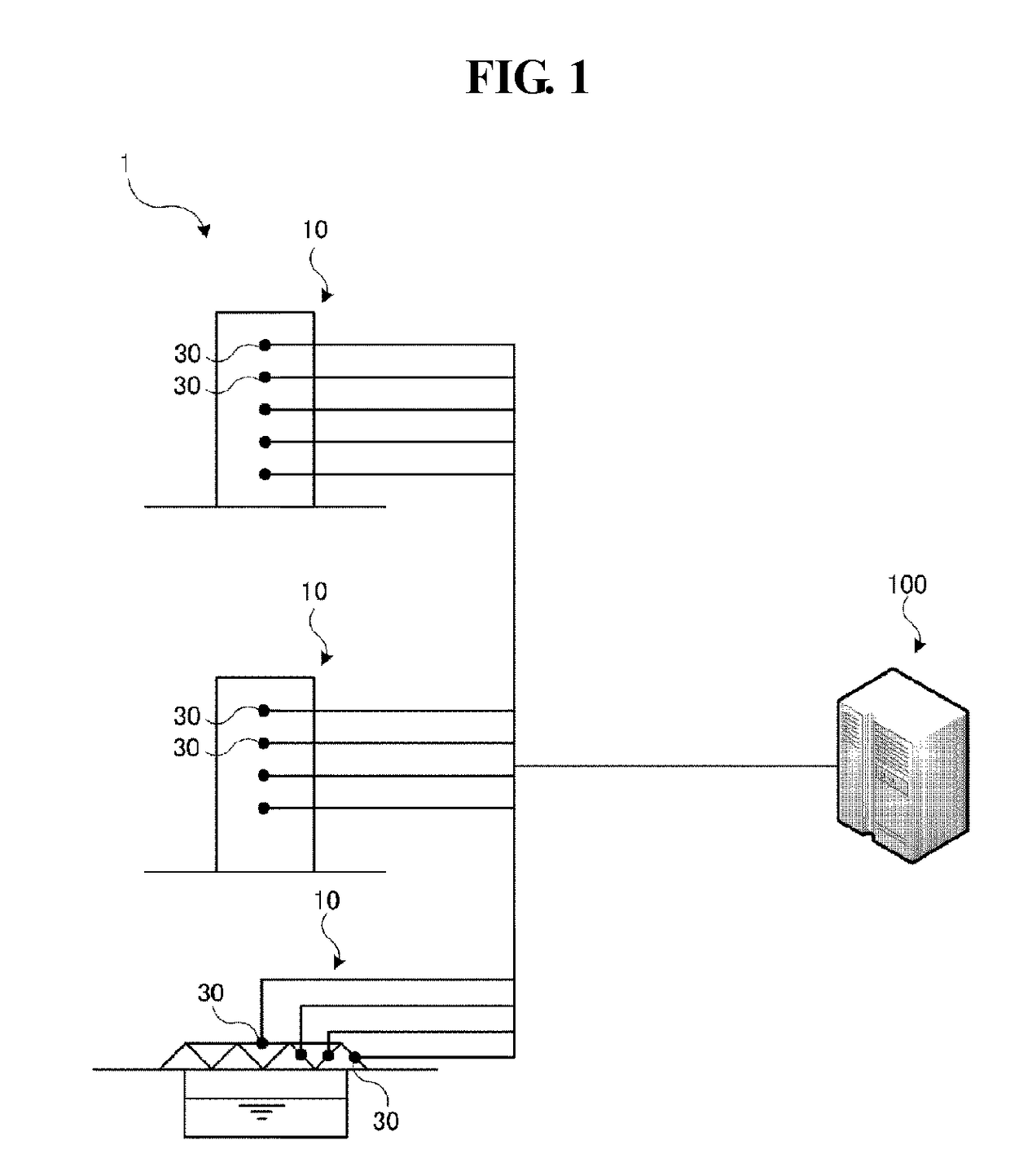
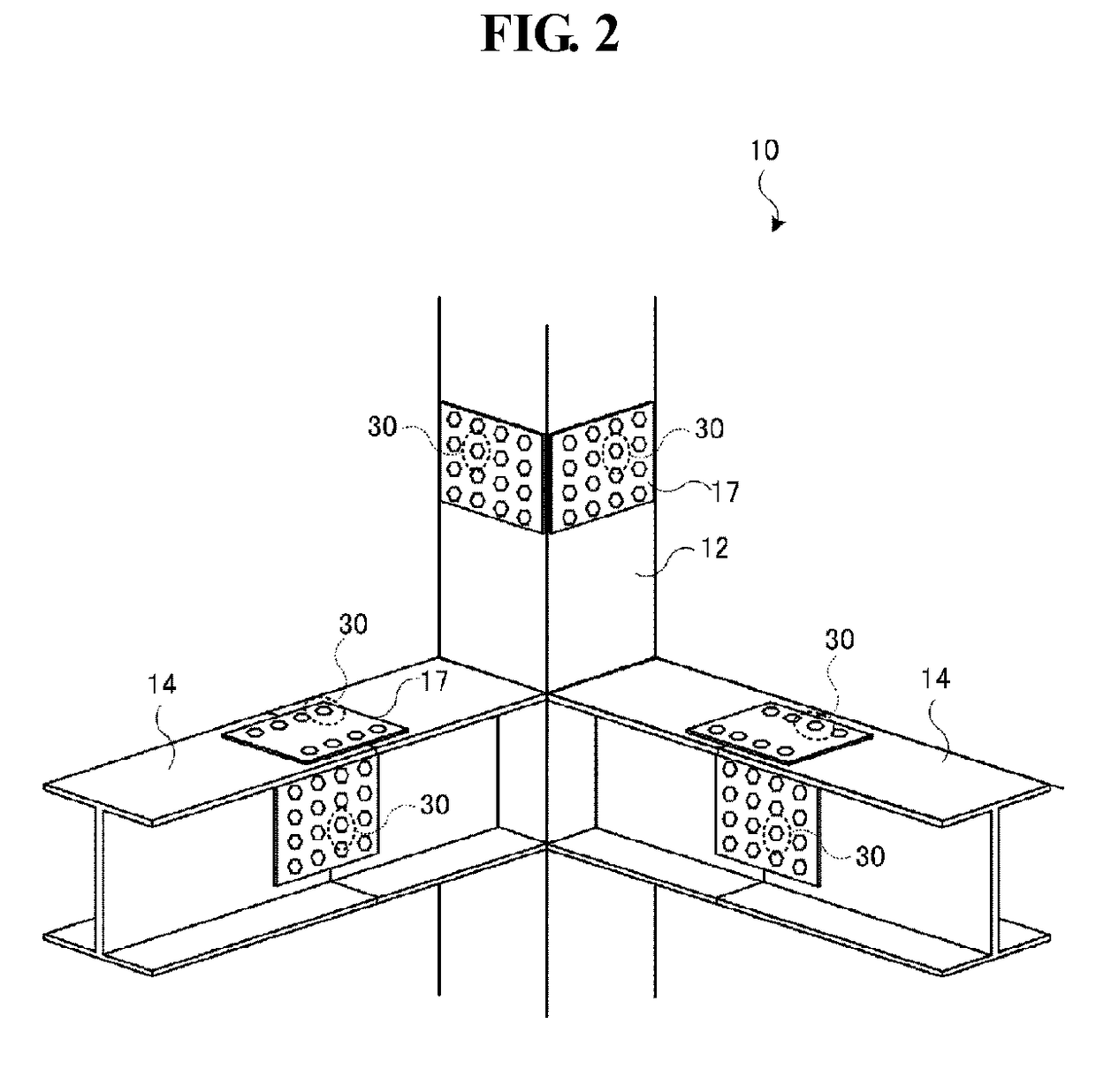
[0083]FIG. 1 illustrates a measuring system 1 of a construction using a conduction-path-equipped member according to an embodiment of the present invention. The measuring system 1 includes a plurality of constructions 10 such as buildings or bridges, a conduction-path-equipped member 30 (for example, a structural material such as H-shaped steel, C-shaped steel, T-shaped steel or I-shaped steel, a screw fastening member, or a fastening member such as a rivet) used as a member to determine a structure when building the constructions 10, and an information collection device 100 to be connected to the conduction-path-equipped member 30 through wire or wireless communication.

[0084]Herein, the conduction-path-equipped member 30 is a male screw body or a female screw body, and may be used for basic structural materials of the constructions 10.

[0085]In detail, as s...


PUM


Abstract

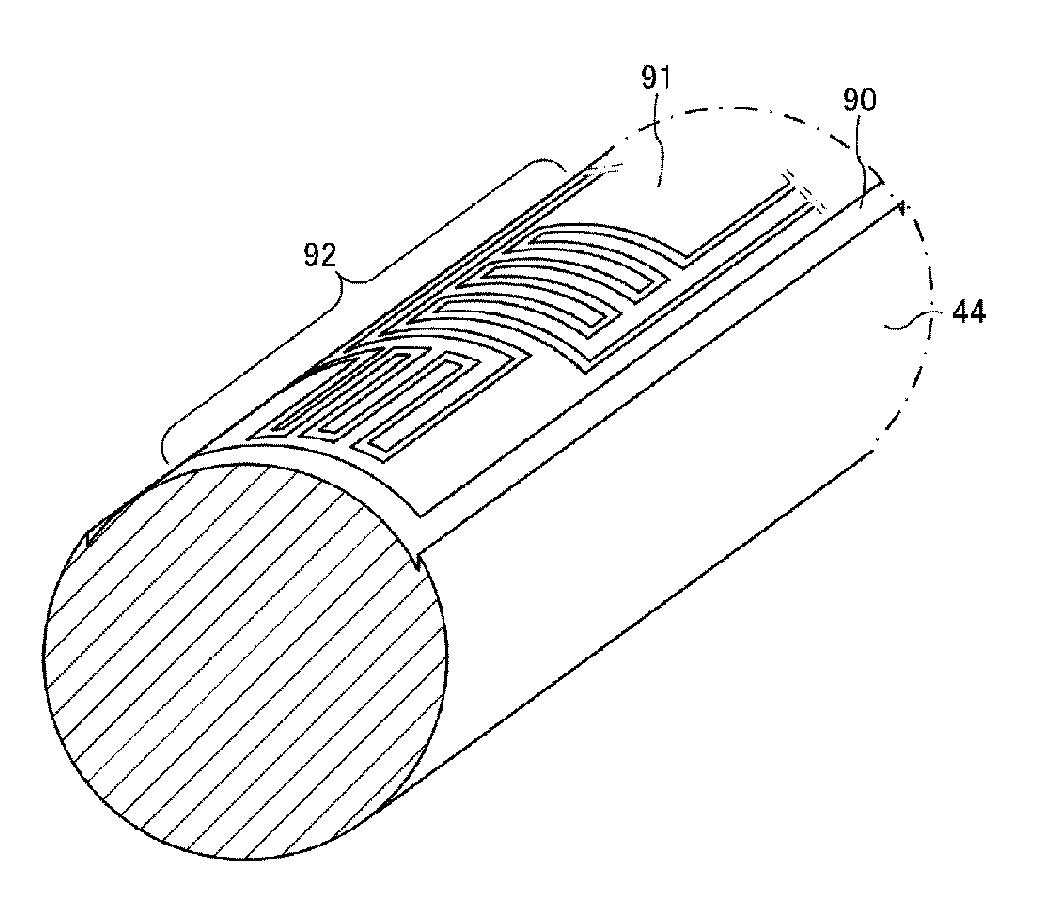
The present invention directly forms, on part of a member to be measured, a conduction path for measuring changes in said member. The present invention thus detects changes such as stress and displacement acting on a conduction-path-equipped member 30 intended for use in a structural member or the like. Consequently, circumstances generating stress in the member can be objectively monitored.

Description

TECHNICAL FIELD[0001]Embodiments of the present invention relate to a structure such as a house, an apartment or a building, an edifice or construction (hereinafter, the edifice and the construction are simply and collectively referred to as the construction) such as a bridge, a steel tower, a railroad, a pipeline, a plant, a power plant, a wind power generator or a solar photovoltaic power generator, or various members such as construction materials or structural materials used for the same, an industrial machine such as construction equipment or a machine tool, or other machines or fastening members constituting the same, or members used in various places, for example, a component such as a spring, a bearing or a linear guide, a variety of transportation such as a rocket, an aircraft, a submarine, a vessel, a subway train, a bus, a truck, a car, a motorcycle, a bicycle and an elevator, office or home appliances, and disposable products, and a method of forming a conduction path to...

Claims


Application Information

Patent Timeline
IPC IPC(8): G01L1/22
CPCG01L1/22G01L5/243G01M5/0083G01L5/0004F16B2031/022Y02B10/30G01L1/2287G01L1/225
Inventor MICHIWAKI, HIROSHI
Owner NEJILAW
Learn More