Electrodynamic Transducer and Method for Manufacturing an Electrodynamic Transducer

Active Publication Date: 2018-03-08
SENNHEISER ELECTRONICS GMBH & CO KG
View PDF16 Cites 4 Cited by
  • Summary
  • Abstract
  • Description
  • Claims
  • Application Information

AI Technical Summary

Benefits of technology

The present invention provides an electroacoustic transducer that can be manufactured easier and more effectively. Specifically, an electrodynamic transducer that can be manufactured more efficiently by using a special assembly procedure that reduces the requirements on tolerances and simplifies the joining process between components. The invention also includes a magnet system module that is easier to manufacture and assemble with the other components. This results in a higher quality transducer that can be joined together better, reducing the scrap rate. Additionally, the invention allows for higher tolerances for single elements and complex geometries, thereby improving the acoustic quality of the transducer.

Problems solved by technology

Even smallest deviations that may occur during assembly will lead to hearable distortion in acoustic reproduction, e.g. due to staggering of the diaphragm when being driven.
The manufacturing of an electrodynamic transducer as describe above is unfavorable, since all method steps need to be executed in an extremely accurate way, and since an exactly accurate arrangement of the single components is required.
Nevertheless, a certain amount of scrap during manufacturing cannot be avoided.
Joining the magnet system by rivets can lead to mechanical abrasion of the material or the riveter, which may pollute the tools used.
This attrition material may also accumulate during assembly at places in the product where it may lead to malfunction.
When the elements of the magnet system are glued together, surplus glue may pollute the centering tool.
This leads to a high amount of scrap and a high maintenance effort.
Therefore low tolerances of the outer diameter of the yoke and the inner diameter of a recess in the chassis are required.
Thus, manufacturing of the chassis may be very cost-intensive.

Method used


Image

  • Electrodynamic Transducer and Method for Manufacturing an Electrodynamic Transducer
  • Electrodynamic Transducer and Method for Manufacturing an Electrodynamic Transducer
  • Electrodynamic Transducer and Method for Manufacturing an Electrodynamic Transducer

Examples


Embodiment Construction

[0037]It is to be understood that the figures and descriptions of the present invention have been simplified to illustrate elements that are relevant for a clear understanding of the present invention, while eliminating, for purposes of clarity, many other elements which are conventional in this art. Those of ordinary skill in the art will recognize that other elements may be desirable for implementing the present invention. However, because such elements are well known in the art, and because they do not facilitate a better understanding of the present invention, a discussion of such elements is not provided herein.

[0038]The present invention will now be described in detail on the basis of exemplary embodiments.

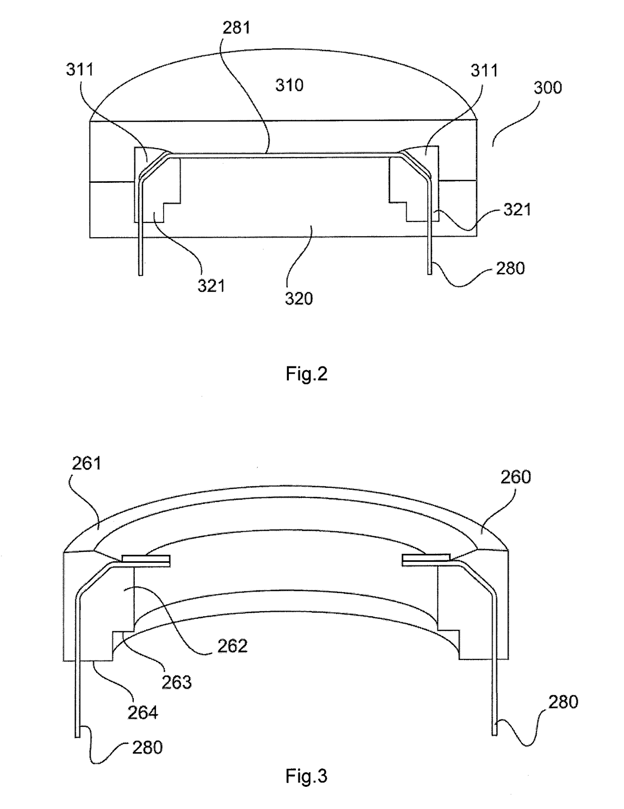
[0039]FIG. 2 shows a schematic view of an injection-molding tool for manufacturing a chassis unit for a membrane system module of an electrodynamic transducer according to a first embodiment.

[0040]A first injection-molding tool 300 comprising a first, upper portion 310 and a...


PUM


Abstract

A method for manufacturing an electrodynamic transducer from a membrane system module and a magnet system module is disclosed. The membrane system module comprises an annular first chassis unit made by injection-molding and a diaphragm fixed thereon. A coil is fixed on a coil seat of the diaphragm. The magnet system module comprises a pole piece, a magnet and a yoke that each have a central hole, and a second chassis unit that is made by injection-molding and that fills the central holes in the pole piece, the magnet and the yoke. It surrounds the yoke at least partially, so that the pole piece, the magnet and the yoke are held. In the transducer, the membrane system module and the magnet system module are plugged together, wherein an annular recess on the lower side of the first chassis unit is arranged on a circumferential shoulder of the second chassis unit. This defines a position of the coil relative to the pole piece, to the magnet and to the yoke of the magnet system module.

Description

[0001]The present application claims priority from German Patent Application No. 10 2016 116 706.1 filed on Sep. 7, 2016.FIELD OF THE INVENTION[0002]It is noted that citation or identification of any document in this application is not an admission that such document is available as prior art to the present invention.[0003]The present invention relates to an electrodynamic transducer and to a method for manufacturing an electrodynamic transducer.BACKGROUND[0004]FIG. 1 shows a schematic drawing of a conventional electrodynamic sound transducer. The transducer 100 comprises a diaphragm 110, a coil 120 and a magnet system 101 consisting of a pole piece 130, a magnet 140 and a yoke 150. The magnet system 101 together with the diaphragm 110 and the coil 120 can be placed and glued in a chassis 160. Further, the elements of the magnet system 101, namely pole piece 130, magnet 140 and yoke 150, can be glued together. Alternatively, the connection can be made by rivets. The coil 120 is a vo...

Claims


Application Information

Patent Timeline
IPC IPC(8): H04R31/00B29C45/14B29C65/48H04R7/18H04R7/12H04R9/02H04R9/06
CPCH04R31/003B29C45/14467B29C65/48H04R31/006H04R7/18H04R7/127H04R9/025H04R9/06H04R2400/11H04R1/06H04R9/02H04R9/041H04R9/045H04R2209/024
Inventor POPPEL, GUNTERKONETZKY, ROBERTMICHAELIS, ANDREFAULHABER, MEIKE
Owner SENNHEISER ELECTRONICS GMBH & CO KG
Why Eureka
Try Eureka