Dry friction damped mechanical and structural metal components and methods of manufacturing the same

Active Publication Date: 2018-03-15
FORD GLOBAL TECH LLC
View PDF1 Cites 1 Cited by
  • Summary
  • Abstract
  • Description
  • Claims
  • Application Information

AI Technical Summary

Benefits of technology

The disclosed invention provides a method and system for increasing the damping capacity of cast metal parts by using dry friction between individual wires of a rope embedded in the part during the casting process. Embedded ropes allow inter-wire friction to occur during part vibration, while a thin layer of metal prevents molten metal from infiltrating the individual wires. The embedded ropes are stable and can undergo relatively large elastic distortions without any noticeable change in contact pressure between the individual wires, resulting in stable damping properties for many metals over a wide range of operating temperatures. The invention can be applied to a broad variety of structures including vehicle suspensions, engine blocks, gas turbines, wind mills, jet engines, and building vibrations.

Problems solved by technology

Mechanical and structural components such as vehicle suspensions, engine blocks, turbine blades and discs, and support structures for motors, pumps, centrifugal machines and the like are commonly subjected to vibration.
When this occurs, these components experience a periodic motion in alternately opposing directions from the position of equilibrium which induces loads that can lead to reduced component life.
Conversely, in other engineering material systems having relatively low damping capacity (such as ductile cast iron, aluminum or other cast metals), the decay of vibration amplitude is very slow.
As an undesirable consequence, such systems are at a higher risk of failure due to fatigue resulting from cyclic variations of the induced stress.
Existing technology for friction dampers for metal parts cannot achieve this goal since current knowledge assumes a constant full slip condition between, for example, a rotor and insert surfaces or between insert and filler surfaces.
In reality, the full slip condition between the part and insert surfaces or between insert and filler surfaces may change with a change in the part temperature due to unavoidable thermal distortion of the sliding interface resulting in a change in contact pressure from its desired optimal value.
Since even a relatively small distortion of an interface between the solid bodies (i.e., continuous inserts) may result in a significant change in contact pressure between them, the deviation of contact pressure from its optimal value may be very large compromising friction damper effectiveness.

Method used


Image

  • Dry friction damped mechanical and structural metal components and methods of manufacturing the same
  • Dry friction damped mechanical and structural metal components and methods of manufacturing the same
  • Dry friction damped mechanical and structural metal components and methods of manufacturing the same

Examples


Embodiment Construction

[0034]In the following figures, the same reference numerals will be used to refer to the same components. In the following description, various operating parameters and components are described for different constructed embodiments. These specific parameters and components are included as examples and are not meant to be limiting.

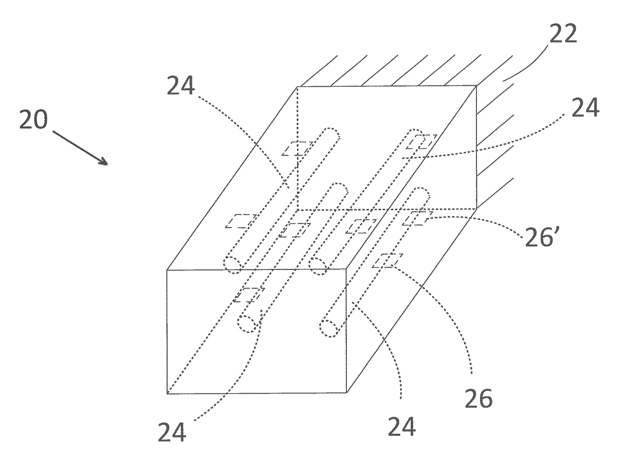
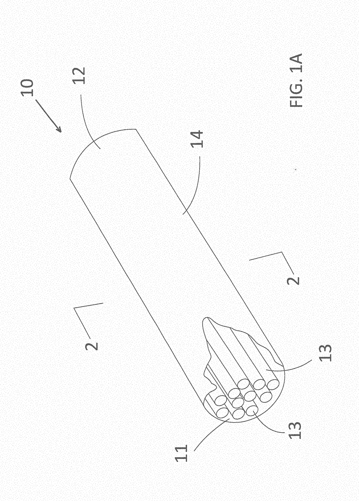
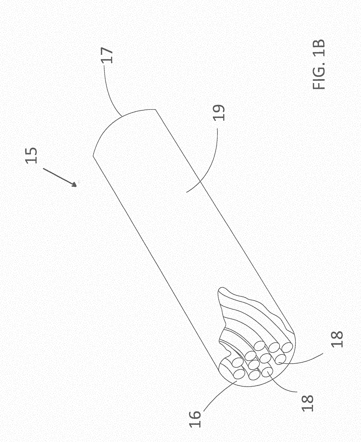
[0035]The accompanying figures and the associated description illustrate the construction and use of vibration-damping ropes according to the disclosed inventive concept. Particularly, FIGS. 1A, 1B and 2 illustrate the vibration-damping rope itself. FIG. 3 illustrates the vibration-damping rope used in a generic component. FIGS. 4A-6B illustrate the vibration-damping rope employed in a brake rotor as an example of how the rope can be used in a component to dampen vibration. FIGS. 7-10 illustrate the vibration-damping rope employed indirectly in an engine block by way of first being formed as part of an insert. The insert is thereafter incorporated into the ...


PUM

PropertyMeasurementUnit
Melting pointaaaaaaaaaa
Stress optical coefficientaaaaaaaaaa
Distributionaaaaaaaaaa

Abstract

A method and system for increasing damping capacity in cast metal parts by utilizing dry friction between individual wires of a sheathed rope is disclosed. The rope is embedded into the part during casting. Sheathing the ropes in a thin layer of the same metal as the casting prevents molten metal from infiltrating individual wires during casting, thus allowing inter-wire friction during the part vibration. There are two ways to distribute the ropes within a part during casting. The first way is to distribute the ropes uniformly across an entire part whereby damping capacity of the metal part increases uniformly as well. The second way of distributing the ropes is to spatially distribute them according to a pattern to increase the damping capacity only in the part regions that have the highest vibration amplitudes or stress during system vibration. Both methods of distribution may be combined in a single part.

Description

TECHNICAL FIELD[0001]The disclosed inventive concept relates to cast metal parts having increased damping capacity. More particularly, the disclosed inventive concept relates to dry friction damped mechanical and structural metal components and methods of manufacturing same. Damping is capacity is increased by providing sheathed cables or ropes comprising plural individual wires that are either linear or twisted relative to one another and are embedded into the part during casting. The strength of the individual wires is preferably higher than that of the casting alloy.BACKGROUND OF THE INVENTION[0002]Mechanical and structural components such as vehicle suspensions, engine blocks, turbine blades and discs, and support structures for motors, pumps, centrifugal machines and the like are commonly subjected to vibration. When this occurs, these components experience a periodic motion in alternately opposing directions from the position of equilibrium which induces loads that can lead to...

Claims


Application Information

Patent Timeline
IPC IPC(8): F16F7/00B22D19/14
CPCF16F7/00F16F2222/04F16F2226/00B22D19/14F16F7/14
Inventor BOILEAU, JAMES MAURICEKARPENKO, YURI ANATOLYOAKWOOD, J. CHRISKOWALOW, PETERDAMMEYER, LAURASWISHER, STEVEN
Owner FORD GLOBAL TECH LLC
Why Eureka
Try Eureka