

Fast settling capacitive gain amplifier circuit
a capacitive gain amplifier and circuit technology, applied in the direction of dc isolation amplifiers, amplifiers with multiple amplifying elements, code conversion, etc., can solve the problems of limited maximum sampling rate or frequency of capacitive gain amplifier circuits, and limit the speed of operation
- Summary
- Abstract
- Description
- Claims
- Application Information
AI Technical Summary
Benefits of technology
Problems solved by technology
Method used
Image

Examples
example 49
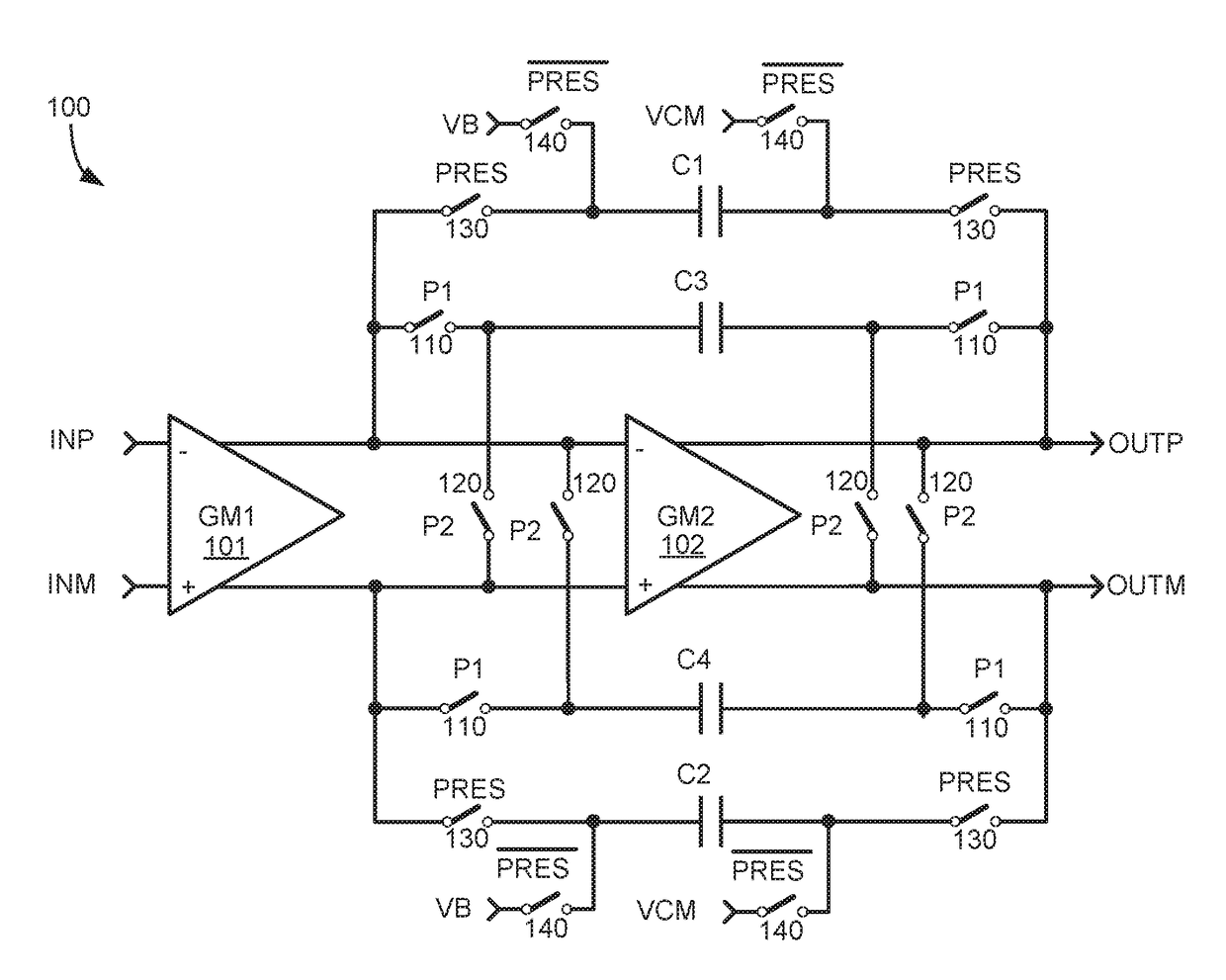
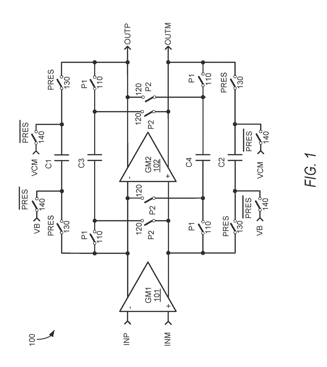
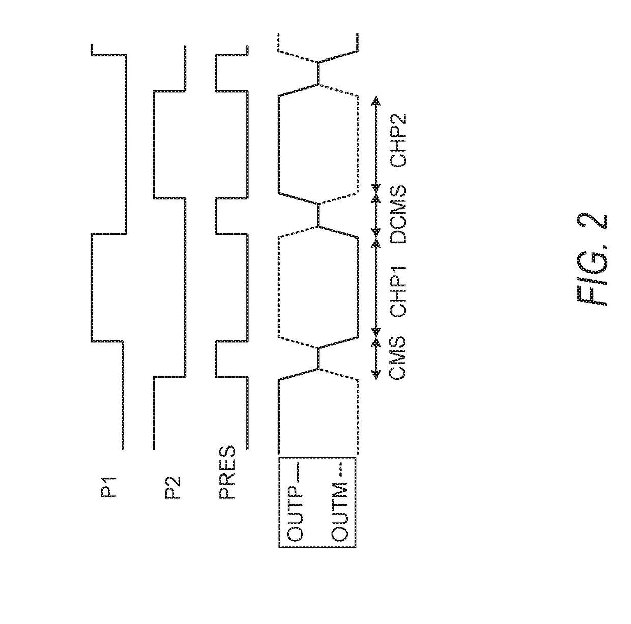
[0211 is a method of capacitive gain amplification using a first output stage differential amplifier circuit and a second output stage differential amplifier circuit, the method comprising: switching in a first set of Miller capacitors between respective outputs and respective inputs of the first output stage differential amplifier circuit during a first phase that resets the first output stage differential amplifier circuit; switching in a second set of Miller capacitors between respective outputs and respective inputs of the first output stage differential amplifier circuit during a second phase that chops a signal being amplified by the first output stage differential amplifier circuit, the switching in of the second set of Miller capacitors being to alternating inputs of the first output stage differential amplifier circuit during successive second phases; and operating both the first output stage differential amplifier circuit and the second output stage differential amplifier ...
example 68
[0230]In Example 68, the subject matter of any one or more of Examples 61-67 optionally include an impedance network disposed between the set of outputs of the second differential amplifier circuit and corresponding inputs of an ADC circuit during the second phase.
[0231]In Example 69, the subject matter of any one or more of Examples 61-68 optionally include a fifth set of switches to respectively couple the set of outputs of the first differential amplifier circuit with the set of inputs of the first differential amplifier circuit to configure the first differential amplifier circuit as a unity gain amplifier during the first phase.
[0232]In Example 70, the subject matter of any one or more of Examples 61-69 optionally include a third chopper circuit coupled between a set of inputs of the capacitive gain amplifier circuit and the set of inputs of the first differential amplifier circuit; and a fourth chopper circuit coupled between the respective output sides of the set of feedback ...
example 78
[0240 is a capacitive gain amplifier circuit to amplify an input signal by a pair of differential amplifier circuits coupled in series, the capacitive gain amplifier circuit comprising: a first differential amplifier circuit, including a set of inputs and a set of outputs; a second differential amplifier circuit, including a set of inputs and a set of outputs; a set of input capacitors coupled with respective inputs of the first differential amplifier circuit, the set of input capacitors having inputs selectively switched to provide a common mode input voltage to the set of inputs of the first differential amplifier circuit during a first phase that resets the first differential amplifier circuit, and to provide a differential input voltage from respective inputs of the capacitive gain amplifier circuit to the set of inputs of the first differential amplifier circuit during a second phase that amplifies a signal by the first differential amplifier circuit and the second differential...
PUM
 Abstract
Description
Claims
Application Information