Reconfigurable display with camera aperture therethrough

a technology of a display and an aperture, applied in the field of display, can solve the problems of difficult locating of one or more cameras or other sensors, minimal mechanical interference, and high cost, and achieve the effect of low cost, easy die-cutting, and low cos

Inactive Publication Date: 2018-03-22
APTIV TECH LTD
View PDF20 Cites 9 Cited by
  • Summary
  • Abstract
  • Description
  • Claims
  • Application Information

AI Technical Summary

Benefits of technology

[0004]Described herein a reconfigurable display that defines an aperture or opening through which a camera can ‘see’ that keeps cost low and is more technically feasible than the aforementioned practice of cutting holes entirely through the display. The proposed solution to the problem stated is to use a modified display stack that defines an aperture for the camera or sensor as created via a cut-out or notch through all display layers except the TFT glass, which defines a window through which the camera sees. The other layers typically consist of plastic molded parts for light dispersion and various film layers that can be easily die-cut to allow for an optical path through the display stack. Layers within the display stack that are printed through a manufacturing process are modified such that elements are not printed in the area desired for the aperture. This may include, for example, a color filter. The camera or any other type of sensor requiring an aperture through the display would be rear-mounted and have a site hole through the created aperture. Through normal control of the display image, the area of TFT reserved for the window can be gated or controlled such that the field-of-view of the camera is minimally obstructed. Optionally, as needed, the area of TFT in the path of the field-of-view could be controlled to alter the light transmission to the camera. By creating an aperture through the display stack by cutting films, modifying the printed elements, and altering the shape of the light dispersion layer while not changing the properties of the TFT glass will allow for shared use of the space by both camera and display while keeping costs low.

Problems solved by technology

The difficulty is locating the one or more cameras or other sensors in such a way that they minimally interfere both mechanically and visually with the desired display features.
Such solutions are either technically difficult to achieve or very expensive due to the cutting of the thin-film-transistor (TFT) glass utilized as one of the many layers that constitute the AMLCD.

Method used


Image

  • Reconfigurable display with camera aperture therethrough
  • Reconfigurable display with camera aperture therethrough
  • Reconfigurable display with camera aperture therethrough

Examples


Embodiment Construction

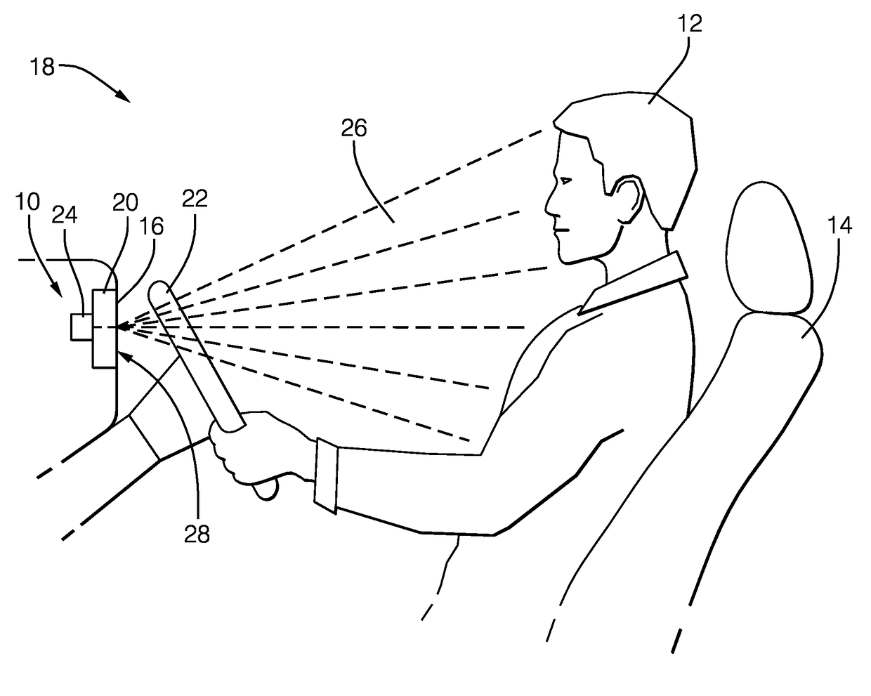
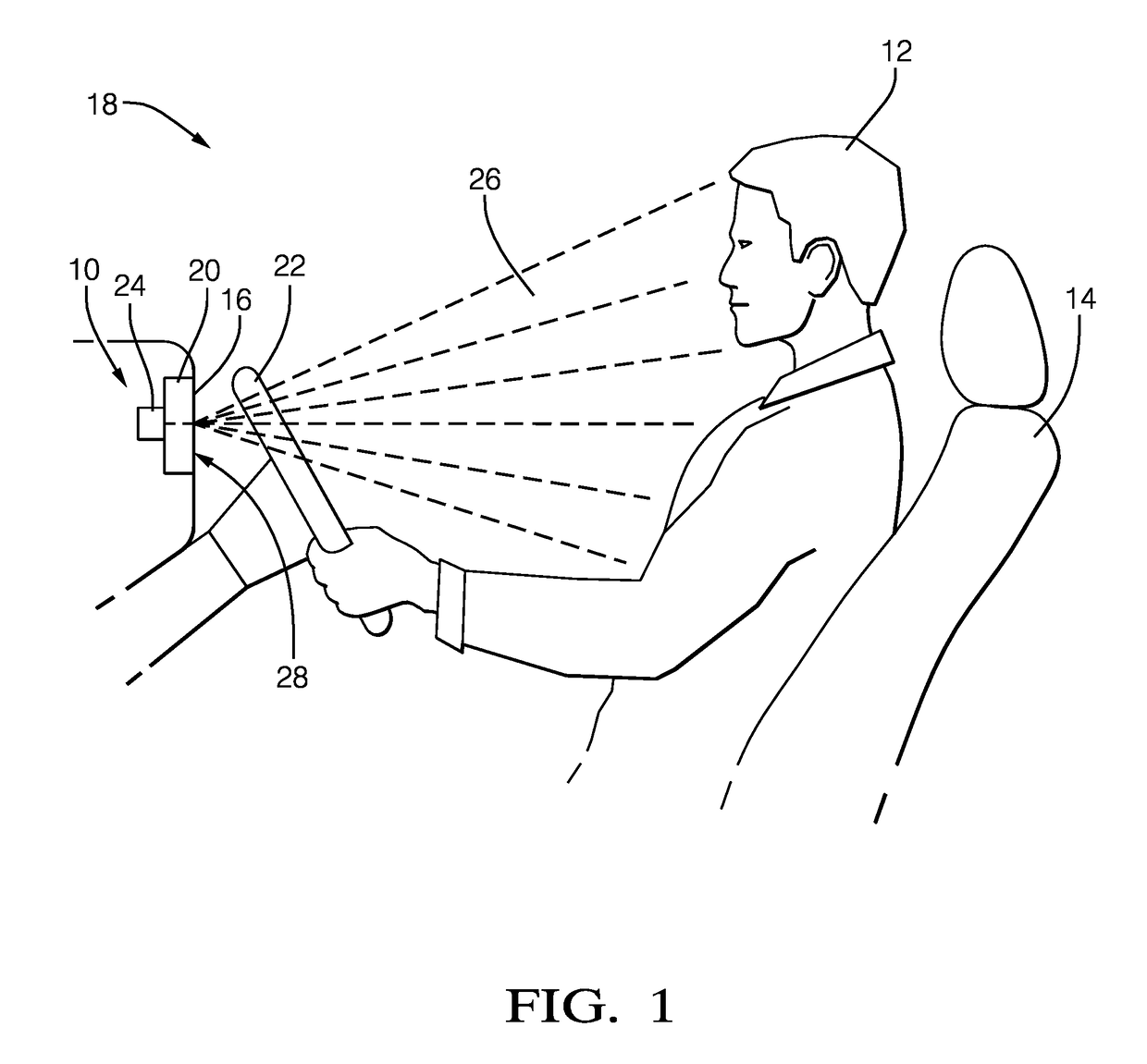
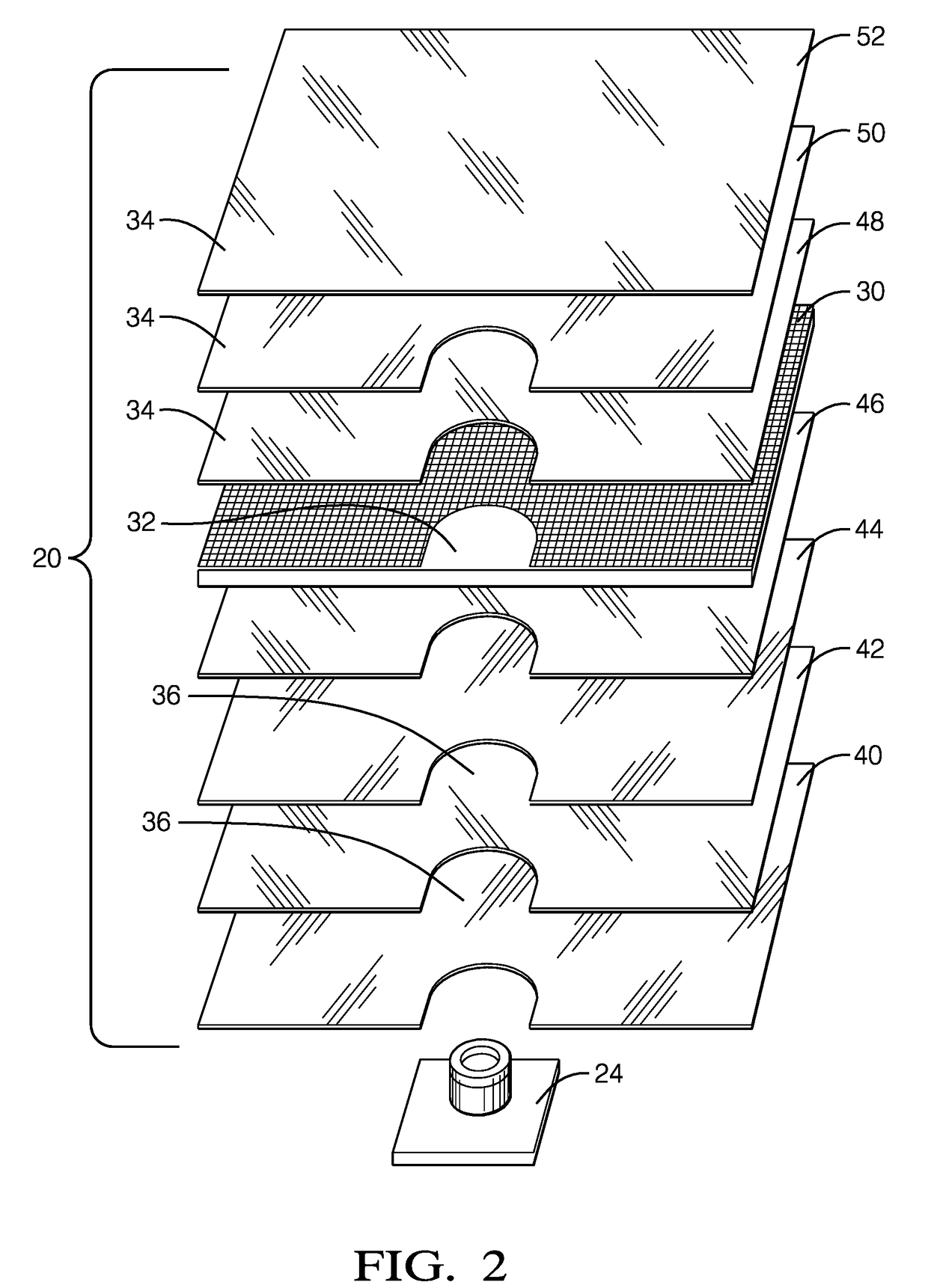
[0010]The proposed solution to the problem stated is to use a modified display stack that includes an aperture for the camera or sensor as created via a cut-out or notch through all display layers except the TFT glass. The other layers consist of plastic molded parts for light dispersion and various film layers that can be easily die-cut to allow for an optical path through the display stack. Layers within the display stack that are printed through a manufacturing process are modified such that elements are not printed in the area desired for the camera aperture. This may include, for example, the color filter. The camera or any other type of sensor requiring an aperture through the display would be rear-mounted and have a site hole through the created aperture. Through normal control of the display image, the area of TFT that shall be transparent for the camera system can be gated by the controller software such that the camera optics is minimally obstructed. Optionally, as needed,...


PUM


Abstract

A reconfigurable display system includes a camera, a thin-film-transistor layer, and a film layer. The camera is located behind a display and oriented to have a field-of-view of a viewable-side of the display. The thin-film-transistor layer of the display defines a window whereby the camera views the field-of-view through the thin-film-transistor layer. The film layer of the display defines an aperture though the film layer, wherein the film layer is positioned so that the aperture is aligned with the window. As a result, the camera views the field-of-view through the aperture and the thin-film-transistor layer.

Description

CROSS-REFERENCE TO RELATED APPLICATION[0001]This application claims the benefit under 35 U.S.C. § 119(e) of U.S. Provisional Patent Application No. 62 / 398,124, filed 22 Sep. 2016, the entire disclosure of which is hereby incorporated herein by reference.TECHNICAL FIELD OF INVENTION[0002]This disclosure generally relates to a display, and more particularly relates to a display that includes an aperture through which a camera can see.BACKGROUND OF INVENTION[0003]A growing number of vehicles employ reconfigurable displays such as an Active Matrix Liquid Crystal Display (AMLCD) or similar technology to convey important vehicle information such as vehicle speed, engine speed (RPMs), fuel level, temperature, and warning indicators to the driver. This display is frequently located in the instrument cluster between the steering wheel and front glass or windshield. More recently, new technology has been competing with this same display space as camera systems are employed to monitor the driv...

Claims


Application Information

Patent Timeline
Patent Type & Authority Applications(United States)
IPC IPC(8): B60R11/04B60Q9/00
CPCB60R11/04B60R2300/8006B60Q9/005B60Q9/008B60K35/00G09F9/30B60K2370/152G02B5/3041B60Y2400/3015G02B2027/0138B60Y2400/92B60K2370/21B60K2370/149B60K2370/176B60W2050/146
Inventor DAVIS, J. ROGERUGLUM, PAUL A.
Owner APTIV TECH LTD
Why Eureka
Try Eureka