
Rotor and motor having rotor

Active Publication Date: 2018-03-22
SHENZHEN JINSHENG SCI & TECH CO LTD
View PDF0 Cites 11 Cited by
  • Summary
  • Abstract
  • Description
  • Claims
  • Application Information

AI Technical Summary

Benefits of technology

The present invention has the following technical effects. It arranges the primary and secondary permanent magnet groups in a way that reduces resistance in the electromagnetic field. The secondary magnets in each group have opposite polarity to the primary and tertiary magnets, so they feed back electric energy to the power supply during rotation. This invention also has a smooth rotor and higher torque, as well as eliminates pulsation torque, which improves power efficiency and saves energy.

Problems solved by technology

Due to the existing of iron core groove tooth of the stator, the torque pulsation caused by tooth space makes the air-gap permeance on the surface of the permanent magnet and the corresponding stator not uniform.
When the rotor rotates, in a state the magnetic circuit reluctance changes, thus causing the torque pulsation.
Thus, the use of electric energy by the motor is not efficient.

Method used


Image

  • Rotor and motor having rotor
  • Rotor and motor having rotor
  • Rotor and motor having rotor

Examples


Embodiment Construction

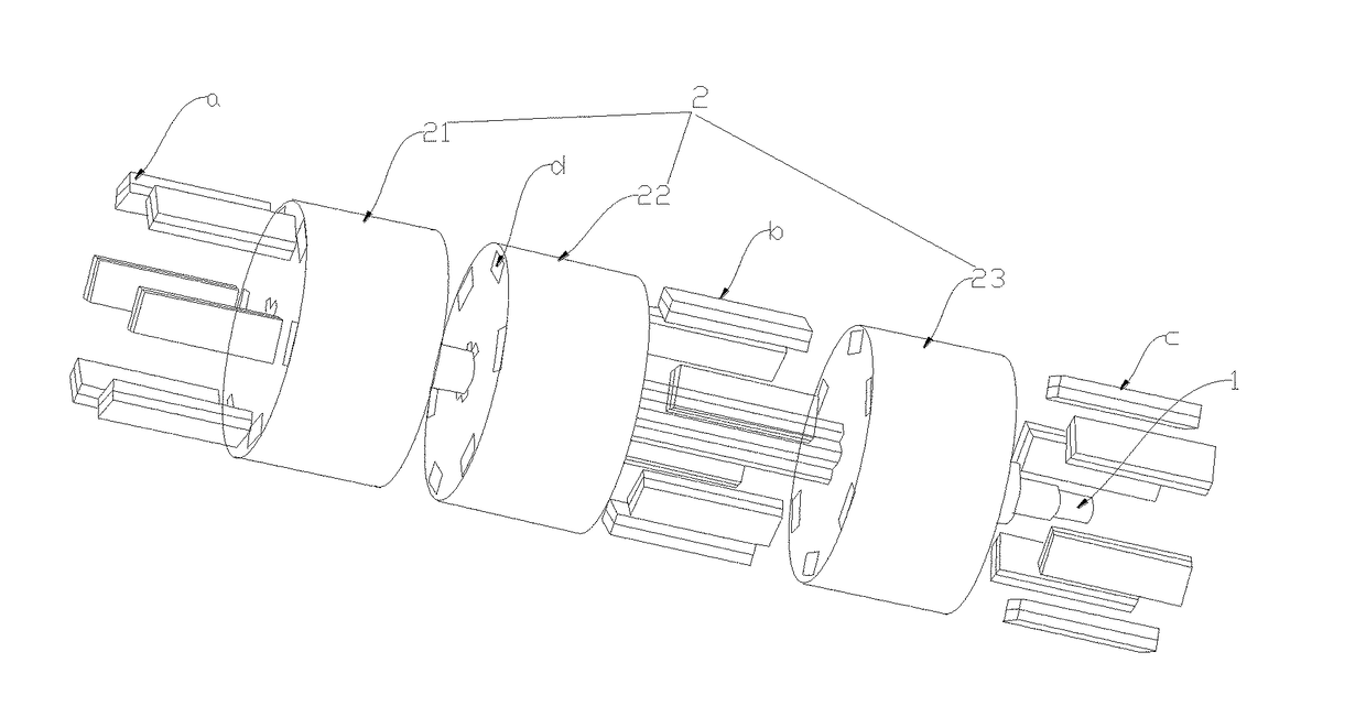
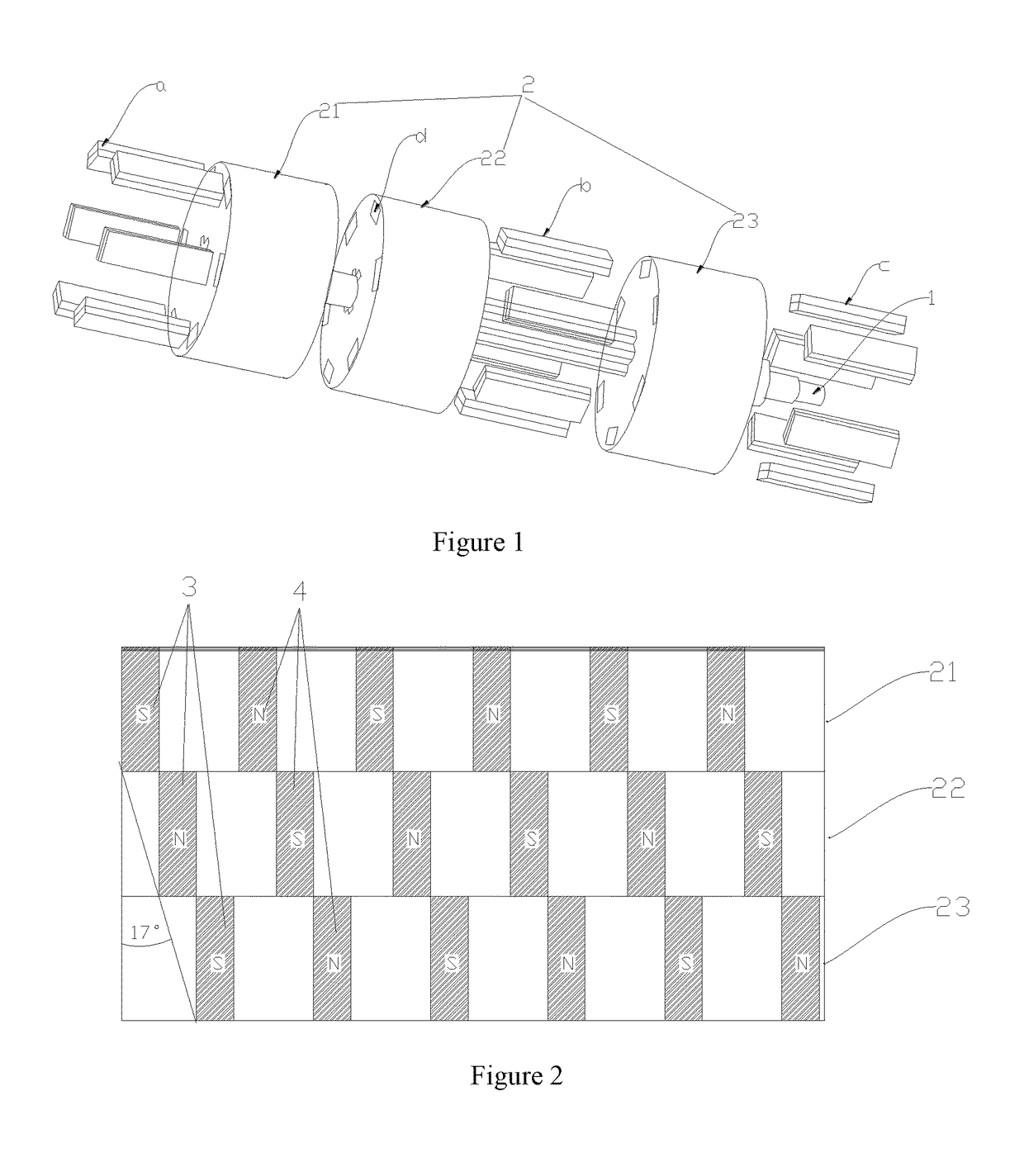
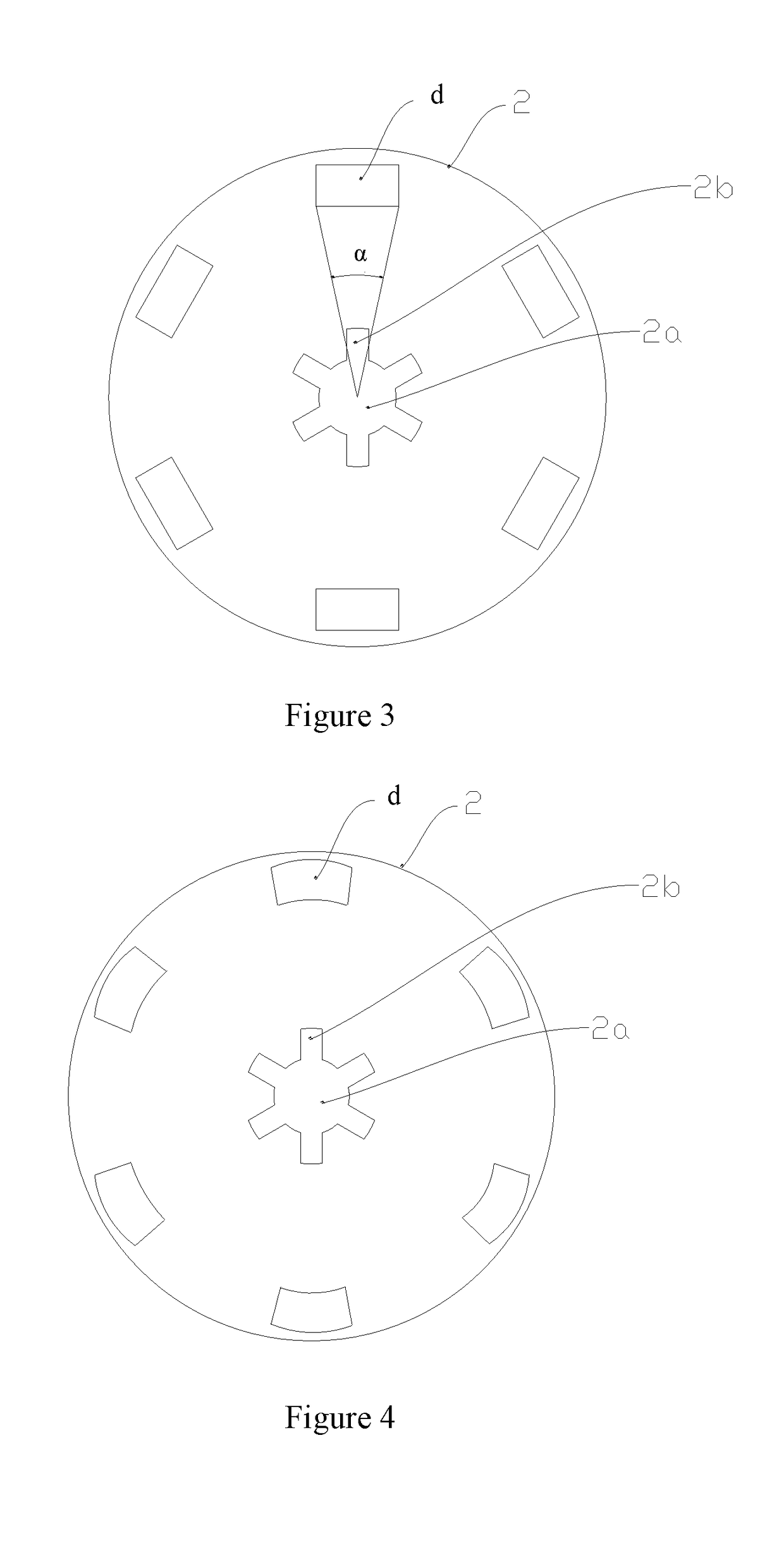
[0025]FIG. 1 shows the rotor in the first embodiment of the present invention, which is mainly used to form the electric motor with the chute stator. Referring to FIG. 2, the rotor comprises shaft 1, magnetic yoke of rotor 2, several primary permanent magnet groups 3, and several secondary permanent magnet groups 4. Several primary permanent magnet groups 3 and several secondary permanent magnet groups 4 are alternatively distributed along the circumference of the said magnetic yoke of rotor 2 at the same interval. The projection of the primary permanent magnet group 3 and that of the secondary permanent magnet group 4 on a plane vertical to the said shaft 1 are adjacent, and their edges overlap.

[0026]The magnetic yoke of rotor 2 is approximately cylindrical. It comprises the first magnetic yoke of rotor 21, the second magnetic yoke of rotor 22 and the third rotor magnetic yoke of rotor 23 connected to shaft 1 in turn. The first magnetic yoke of rotor 21, the second magnetic yoke of...


PUM


Abstract

The present invention provides a kind of rotor and a motor with the rotor. The rotor comprises a shaft, a magnetic yoke of rotor, several primary permanent magnet groups and several secondary permanent magnet groups. The said several primary permanent magnet groups and the said several secondary permanent magnet groups are alternatively distributed along the circumference of the said magnetic yoke of rotor at the same interval. The projection of the said primary permanent magnet group and that of the said secondary permanent magnet group on a plane vertical to the said shaft are adjacent, and their edges overlap. The present invention can reduce torque pulsation caused by the electromagnetic factors, and increase the external work of torque. Therefore, it has good effects on improving power efficiency of the motor and saving energy.

Description

TECHNICAL FIELD[0001]The present invention relates to the electromagnetic field, in particular a rotor and motor with the rotor.BACKGROUND OF THE INVENTION[0002]Due to electromagnetic factors, the influence of tooth space, current commutation, inductive reaction and others of the brushless permanent magnet brushless motor with the existing technology, a strong pulsating torque is produced. The torque pulsation caused by electromagnetic factors is the torque pulsation due to the interaction between stator current and rotor magnetic field, which is directly related to current waveform, counter EMF waveform and air gap flux density. Under ideal conditions, the stator current is square wave, the counter EMF waveform is trapezoidal, the flat-top width is 120° electrical angle, and the electromagnetic torque is constant. In the actual motor, because of the reason of design and manufacturing, the counter EMF waveform may not be trapezoidal wave, and the flat-top width may not be 120° elect...

Claims


Application Information

Patent Timeline
IPC IPC(8): H02K16/02H02K1/16H02K1/27H02K1/28H02K21/14H02K3/28
CPCH02K16/02H02K1/16H02K1/276H02K1/28H02K21/14H02K3/28H02K2201/06
Inventor CHEN, KENNYZHANG, HUIMING
Owner SHENZHEN JINSHENG SCI & TECH CO LTD
Learn More