Mr compatible puncture catheter

a technology of puncture catheter and mri, which is applied in the direction of catheters, magnetic variable regulation, instruments, etc., can solve the problems of high current density in the tissue, high safety risks for patients, and high current density of the tissue, so as to reduce the number of components, simplify the design, and facilitate the manufacture.

a technology of puncture catheter and mri, which is applied in the direction of catheters, magnetic variable regulation, instruments, etc., can solve the problems of high current density in the tissue, high safety risks for patients, and high current density of the tissue, so as to reduce the number of components, simplify the design, and facilitate the manufacture.

US20180085027A1Inactive Publication Date: 2018-03-29IMRICOR MEDICAL SYST

Image

  • Mr compatible puncture catheter
  • Mr compatible puncture catheter
  • Mr compatible puncture catheter

Examples


Embodiment Construction

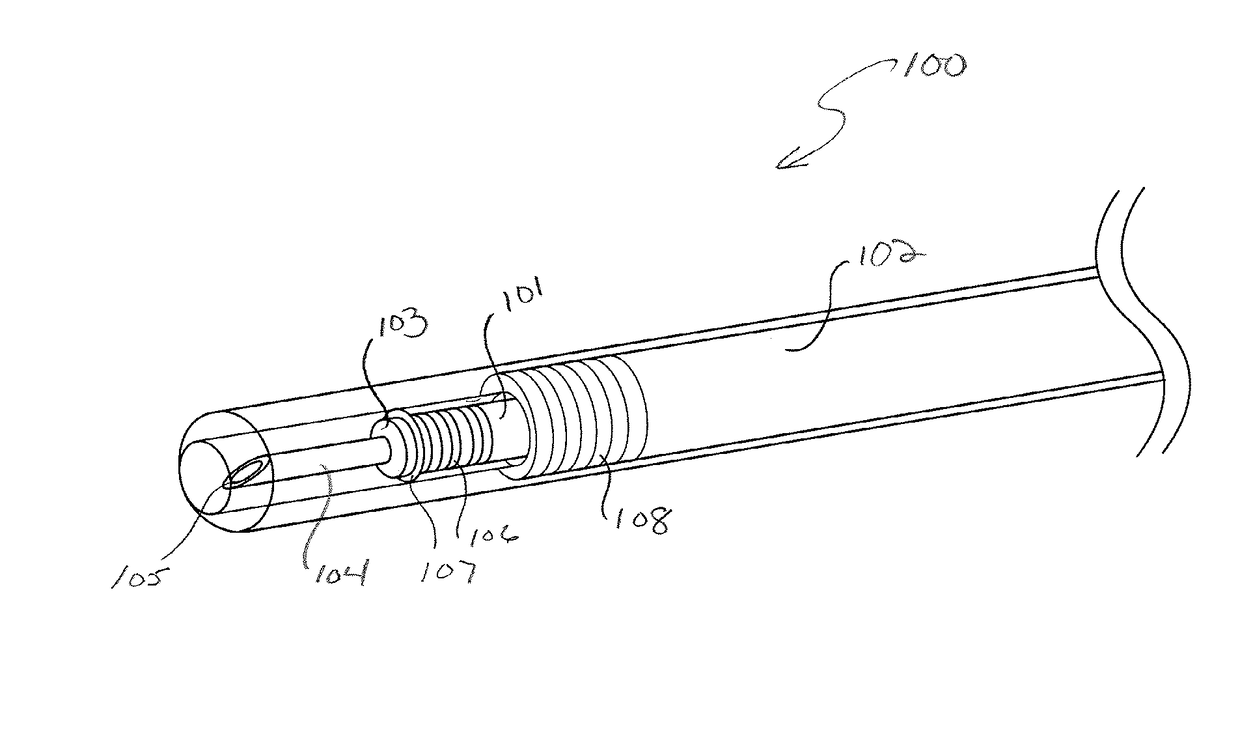
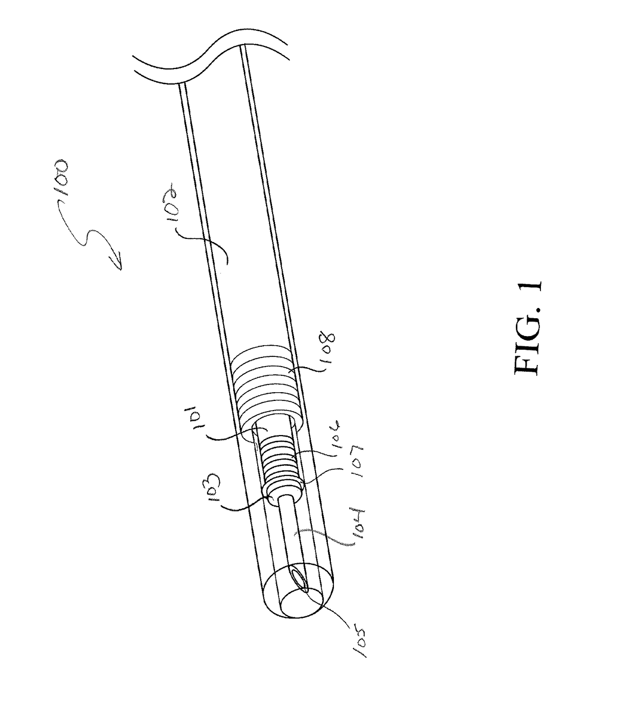
[0044]Referring now to the figures, FIG. 1 shows the distal end 100 of a first aspect of the invention. The injection catheter includes an inner shaft 101 that slides within an outer shaft 102. The inner shaft 101 is a long hollow tube that may consist of a braided catheter construction or a simple polymer extrusion. A puncture tip 103 is operably connected to the distal tip of the inner shaft 101. The puncture tip 103 has a small, short cannula 104 fixedly attached on its distal surface. The cannula extends distally from the puncture tip and is a hollow tube that has a sharpened tip 105. The cannula is similar in shape to the distal tip section of a traditional transseptal needle. The connection between the puncture tip 103 and the inner shaft 101 is such that the lumen of the cannula is continuous with the lumen of the inner shaft. The inner diameter of the cannula lumen is preferably smaller than the inner diameter of the inner shaft lumen, but they could be the same size, or the...


PUM


Abstract

An MR compatible injection catheter is provided. The MR compatible injection catheter includes an inner shaft; an outer shaft circumferentially surrounding the inner shaft; and a means for actively tracking the catheter in a patient within a MRI. The means for actively tracking the catheter includes two or more tracking coils in the outer shaft. The inner shaft is configured to move relative to the outer shaft and includes an inner tube circumferentially surrounded by an outer tube.

Description

FIELD OF THE INVENTION[0001]This invention relates to deflectable medical catheters. More particularly, this invention is related to medical injection catheters.BACKGROUND OF THE INVENTION[0002]Traditionally, deflectable medical catheters have been used in interventional procedures to deliver therapies, such as RF energy, or implantables, such as leads or valves, into the body. Medical catheters have also been used for imaging and diagnostic purposes. Additionally, medical catheters, such as those with balloons, have been used to modify a patient's anatomy, such as during a structural heart application. An emerging catheter-based therapy is the delivery of liquids into tissue. An example of such a therapy is chemo-ablation, which is the destruction of cells via delivery of ethanol or a similar cytotoxic liquid into tissue. Chemo-ablation could be used to replace RF ablation for arrhythmia modification or for targeted chemotherapy of tumors. Another example is stem cell therapy, in w...

Claims


Application Information

Patent Timeline
29 Mar 2018
Publication
US20180085027A1
IPC
A61B5/06; A61M25/01; A61M25/06; A61B5/04; A61M25/00; G01R33/28
CPC
A61B5/062; A61M25/0127; A61M25/06; A61B5/04; A61M25/0084; G01R33/287; A61M2025/0166; A61M2205/3303
Inventors
KIMMEL, SCOTT; WEDAN, STEVEN R.