Methods and systems for coolant system

a technology of coolant system and method, applied in the direction of fluid gearing, machine/engine, fluid gearing, etc., can solve the problems of affecting affecting the reliability of the diagnosis, and the inability to provide adequate cabin cooling, etc., to achieve the effect of reducing the difficulty of refrigerant level, reducing the accuracy of the results, and reducing the time required

Active Publication Date: 2018-03-29
FORD GLOBAL TECH LLC
View PDF9 Cites 14 Cited by
  • Summary
  • Abstract
  • Description
  • Claims
  • Application Information

AI Technical Summary

Benefits of technology

[0004]In one example, the above issues may be better addressed by a method for a vehicle air conditioning system comprising: estimating a target coolant flow rate through a coolant circuit based on a cooling demand at each of an air-conditioning condenser, a charge air cooler (CAC) and a transmission oil cooler (TOC) of the coolant circuit; modeling a reference air-conditioning (AC) head pressure in a refrigerant circuit coupled to the condenser based on each of the target coolant flow rate and a coolant temperature; indicating degradation of the refrigerant circuit responsive to the reference AC head pressure relative to an actual AC head pressure; and in response to the indication, adjusting a ratio of coolant flow through the condenser relative to the CAC. In this way, refrigerant loss may be better identified and addressed.
[0005]As an example, each of a condenser of an AC system and a CAC may be coupled to distinct branches of a coolant circuit downstream of a proportioning valve, coolant directed into the circuit via a coolant pump. The condenser may be further coupled to a refrigerant circuit of the AC system. The AC condenser may be positioned towards a rear end of the under-hood area. During vehicle operation, as driver demand and cabin cooling demand changes, the apportioning of coolant flow to each branch may be varied. For example, when cabin cooling is demanded, a desired coolant temperature is determined. Then, by referring a 2D map or model that maps a relationship between the coolant flow rate, the desired coolant temperature, and an AC head pressure, taking into account parasitic losses, a target coolant flow rate through the AC condenser may be determined (as the point of minima of the asymptote of the 2D map). In particular, there may be a coolant flow rate above which the change in coolant temperature is not significant due to an increase in parasitic losses at the CAC. This coolant flow rate may be set as the desired coolant flow rate through the AC loop. In addition, a corresponding reference AC head pressure may be determined. Based on an error between the actual AC head pressure and the expected reference AC head pressure, refrigerant circuit issues may be identified, distinguished, and accordingly addressed. For example, when the actual head pressure remains less than the reference head pressure over a longer duration (resulting in a larger integrated error), it may be determined that the refrigerant line is pinched or clogged. Accordingly, coolant flow through the condenser may be reduced. As another example, when the actual head pressure remains less than the reference head pressure over a shorter duration (resulting in a smaller integrated error), it may be determined that the refrigerant line is leaking. Accordingly, coolant flow through the condenser may be increased. If the actual head pressure exceeds the reference head pressure, it may be determined that the AC condenser is working harder than expected. Accordingly, coolant flow through the condenser may be increased to improve AC cooling.
[0006]In this way, existing components may be used to monitor an AC system and more reliably diagnose AC system issues. By modeling the expected head pressure of the AC system and the comparing it to the actual pressure, the diagnostics can be performed in a shorter amount of time while relying on fewer components without compromising the accuracy of the results. In addition, erroneous diagnoses are reduced. By better distinguishing AC system errors, appropriate diagnostic codes may be set and mitigating actions may be performed in a timely manner. Overall, engine cooling performance is improved.

Problems solved by technology

However, the inventors herein have identified potential issues with such coolant systems.
As one example, if there is a loss of refrigerant from the AC system, adequate cabin cooling may not be provided.
However, due to the AC system having the refrigerant mass split into liquid and gas states at any given time, and different regions of the AC system being at different temperatures at any given time, it may be difficult to diagnose the refrigerant level.
As such, the drop in AC performance may alternatively be due to a temporary obstruction in refrigerant flow, such as due to a pinched line.
However, for such diagnoses to be effective, the AC system may need to stabilize for a duration.
As such, this may be difficult due to the limited access to the AC evaporator which tends to be deep within a vehicle's HVAC unit, under the instrument panel.
Errors in reading the evaporator frosting pattern can result in incorrect diagnoses.
In addition, the need for a sight glass adds significant cost.
Consequently, in response to degraded AC performance, a service technician may erroneously replace AC components (such as the compressor, the condenser, a thermal expansion valve. an accumulator, etc.) instead of checking the fittings for a leak and adding refrigerant to the AC system.
For example, when the actual head pressure remains less than the reference head pressure over a longer duration (resulting in a larger integrated error), it may be determined that the refrigerant line is pinched or clogged.
As another example, when the actual head pressure remains less than the reference head pressure over a shorter duration (resulting in a smaller integrated error), it may be determined that the refrigerant line is leaking.

Method used


Image

  • Methods and systems for coolant system
  • Methods and systems for coolant system
  • Methods and systems for coolant system

Examples


Embodiment Construction

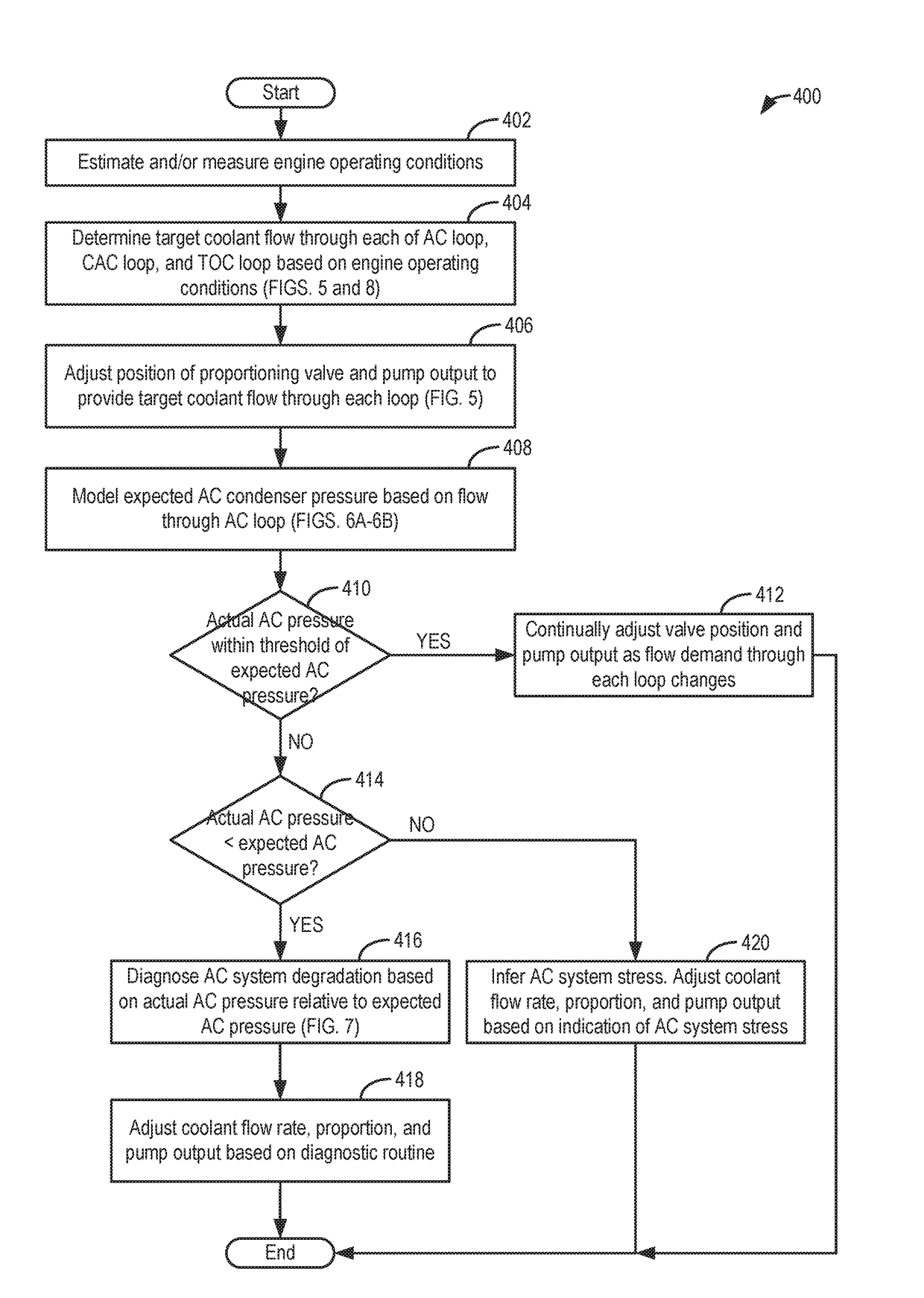
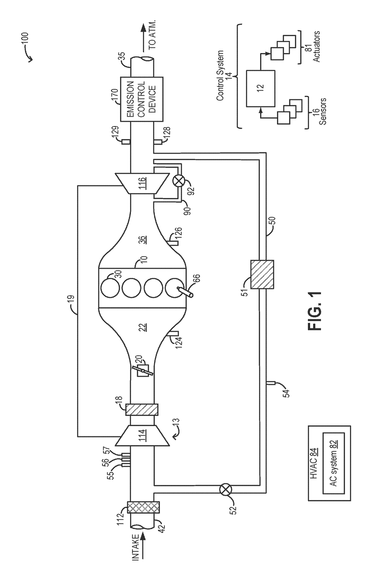
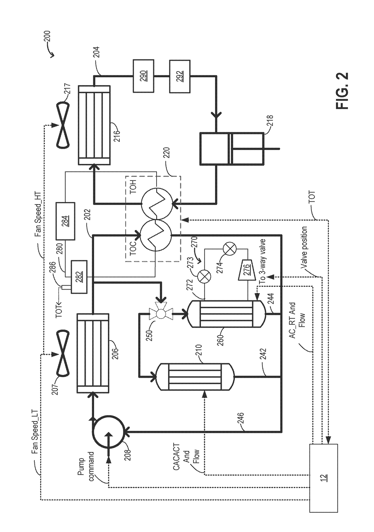
[0017]Methods and systems are provided for improving the performance of components cooled by an engine coolant system, such as the coolant system of FIG. 2 coupled to the engine system of FIG. 1. The coolant system may be operated in one of a plurality of operating states, the coolant system transitioned between the different states responsive to engine operating conditions and changes in cooling demand (as shown at FIG. 3). An engine controller may be configured to perform a control routine, such as the example routine of FIGS. 4-5, to coordinate adjustments to a coolant pump output and the position of a proportioning valve to vary a flow of coolant through the various components of the coolant system to meet cooling demand with reduced parasitic losses. For example, the controller may refer to a map, such as the example maps of FIGS. 6A-6B, to determine a pump output and a coolant flow rate where air conditioning performance is optimized. In addition, the controller may adjust the...


PUM


Abstract

Methods and systems are provided for controlling coolant flow through parallel branches of a coolant circuit including an AC condenser and a charge air cooler. Flow is apportioned responsive to an AC head pressure and a CAC temperature to reduce parasitic losses and improve fuel economy. The flow is apportioned via adjustments to a coolant pump output and a proportioning valve.

Description

FIELD[0001]The present application relates to methods and systems for controlling a flow of coolant through multiple engine components.BACKGROUND AND SUMMARY[0002]Vehicle systems may include multiple coolant loops for circulating coolant through distinct sets of engine components. The coolant flow may absorb heat from some components (thereby expediting cooling of those components) and transfer the heat to other components (thereby expediting heating of those components). For example, a high temperature coolant loop may circulate coolant through an engine to absorb waste engine heat. The coolant may also receive heat rejected from one or more of an EGR cooler, an exhaust manifold cooler, a turbocharger cooler, and a transmission oil cooler. Heat from the heated coolant may be transferred to a heater core (for heating a vehicle cabin), and / or dissipated to the atmosphere upon passage through a radiator including a fan. As another example, a low temperature coolant loop may circulate ...

Claims


Application Information

Patent Timeline
Patent Type & Authority Applications(United States)
IPC IPC(8): F02B29/04F01P3/20F01M5/00B60H1/00B60H1/32
CPCF02B29/0493F01P3/20F02B29/0443F01M5/002B60H2001/3276B60H1/00978B60H1/3211B60H2001/3251B60H2001/3258B60H1/00885B60H1/00271B60H1/3227F01P7/14F02B29/0425F16H41/30F16H57/0412F01P2007/146F01P2050/22F01P2060/12F01P2060/14B60H2001/3279B60H2001/3283F01P2060/02B60H1/3208B60H2001/3266Y02T10/12
Inventor BIDNER, DAVID KARLBONKOSKI, PHILLIPROLLINSON, JAMES C.HAMILTON, HUGHREJETI, SITARAM
Owner FORD GLOBAL TECH LLC
Why Eureka
Try Eureka