Real time calibration for time-of-flight depth measurement

a real-time calibration and depth measurement technology, applied in the field of time-of-flight depth measurement systems, can solve the problems of insufficient time-consuming process, and inability to provide a full coverage of physical envelope, and achieve the effect of increasing operation overhead

Active Publication Date: 2018-04-05
MAGIC LEAP
View PDF3 Cites 27 Cited by
  • Summary
  • Abstract
  • Description
  • Claims
  • Application Information

AI Technical Summary

Benefits of technology

[0005]Conventional time-of-flight depth measurement systems can be susceptible to variations in processes, operating voltages, and thermal conditions. For example, the system might potentially be modified if the thermal conditions (T) or the operating voltages (V) of each of the components were modified. In addition, the TOF measurements can also be affected by the frame rate of the camera. These variations might be dependent on the process (P) of each of the components. Although it might possible to study the nature of the PVT effect and prepare a model to compensate for the errors, this process is time-consuming and may not necessarily provide a full coverage of the physical envelope. Further, a calibration of full range depth measurement is undesirable, because it can take many frames and increases operation overhead.

Problems solved by technology

Conventional time-of-flight depth measurement systems can be susceptible to variations in processes, operating voltages, and thermal conditions.
Although it might possible to study the nature of the PVT effect and prepare a model to compensate for the errors, this process is time-consuming and may not necessarily provide a full coverage of the physical envelope.
Further, a calibration of full range depth measurement is undesirable, because it can take many frames and increases operation overhead.
Further, the overhead in power consumption or dedicated feedback pixels is limited.

Method used


Image

  • Real time calibration for time-of-flight depth measurement
  • Real time calibration for time-of-flight depth measurement
  • Real time calibration for time-of-flight depth measurement

Examples


Embodiment Construction

[0033]Embodiments of the present invention provide a system and method that enable TOF depth measurement with calibration to provide high accuracy using optical feedback and fast image processing. A range of depth measurements can be calibrated for each frame with minimal effect on sensor performance and power consumption.

[0034]The description below is presented with reference to a series of drawing figures enumerated above. These diagrams are merely examples, and should not unduly limit the scope of the claims herein. In connection with the various aspects illustrated and described, one of ordinary skill in the art would recognize other variations, modifications, and alternatives.

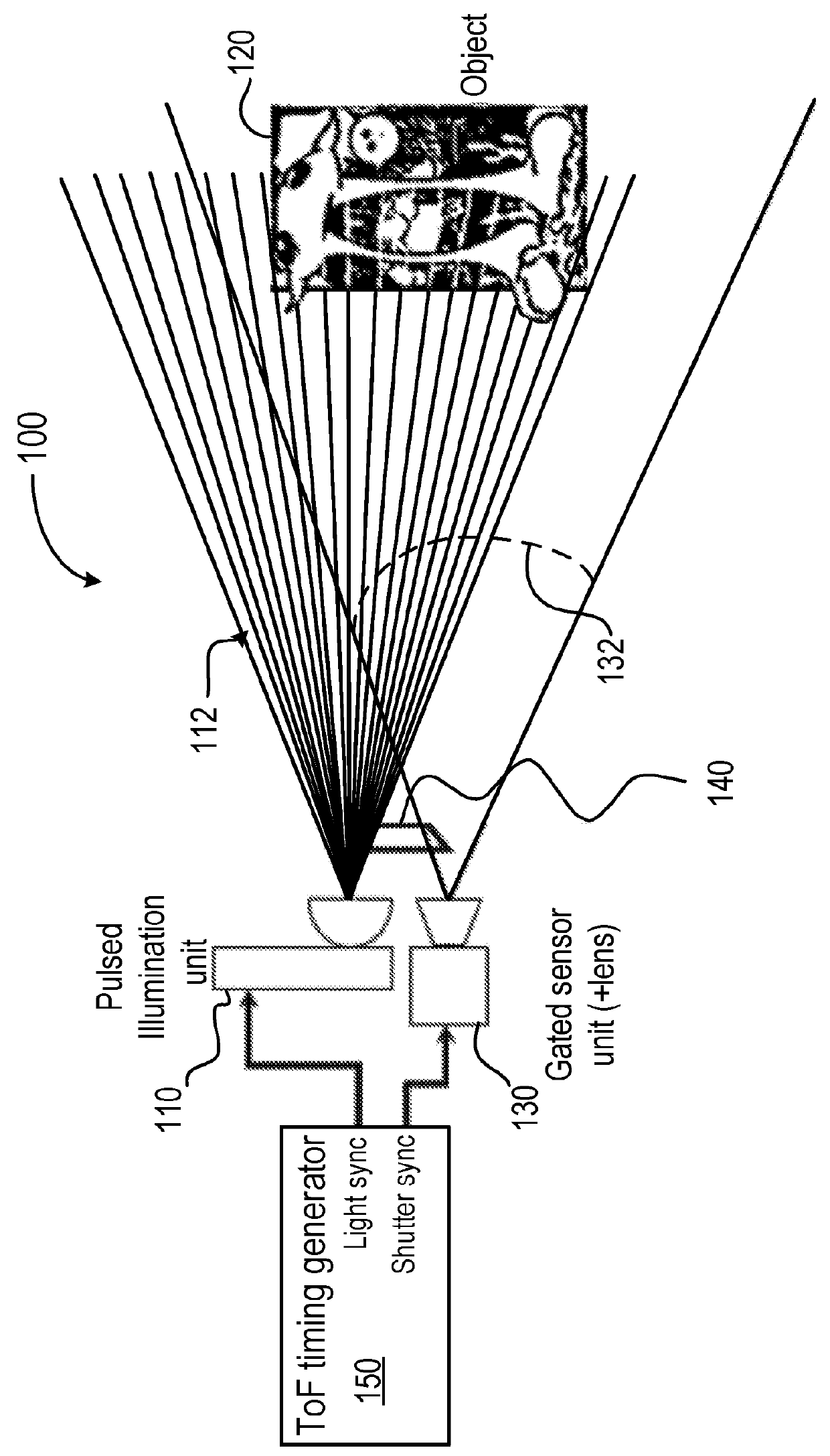
[0035]FIG. 1 is a diagram illustrating a time-of-flight (TOF) imaging system for depth measurement according to an embodiment of the present invention. As shown in FIG. 1, a time-of-flight (TOF) imaging system 100, also referred to as a TOF digital camera, includes an illuminator 110 to transmit light puls...


PUM


Abstract

A method for determining a distance to a target object includes transmitting light pulses to illuminate the target object and sensing, in a first region of a light-sensitive pixel array, light provided from an optical feedback device that receives a portion of the transmitted light pulses. The feedback optical device includes a preset reference depth. The method includes calibrating time-of-flight (TOF) depth measurement reference information based on the sensed light in the first region of the pixel array. The method further includes sensing, in a second region of the light-sensitive pixel array, light reflected from the target object from the transmitted light pulses. The distance of the target object is determined based on the sensed reflected light and the calibrated TOF measurement reference information.

Description

CROSS-REFERENCES TO RELATED APPLICATIONS[0001]This application claims priority to U.S. Provisional Patent Application No. 62 / 402,770, filed on Sep. 30, 2016, the content of which is hereby incorporated by reference in its entirety for all purposes.FIELD OF THE INVENTION[0002]Embodiments of the present invention relate generally to time-of-flight (TOF) depth measurement systems.BACKGROUND OF THE INVENTION[0003]A time-of-flight (TOF) camera is a range imaging camera system that resolves distance based on the speed of light, measuring the time-of-flight of a light signal between the camera and the subject for each point of the image. With a time-of-flight camera, the entire scene is captured with each laser or light pulse. Time-of-flight camera products have become popular as the semiconductor devices became fast to support such applications. Direct Time-of-Flight imaging systems measure the direct time-of-flight required for a single laser pulse to leave the camera and reflect back on...

Claims


Application Information

Patent Timeline
Patent Type & Authority Applications(United States)
IPC IPC(8): G06T7/521G01S17/08G01S7/483G01S17/89G01S17/894
CPCG06T7/521G01S17/08G01S7/483G06T2207/10004G01S7/4813G01S7/497G01S17/894G01S17/89
Inventor COHENPELLMAN, ASSAFMAZOR, SHAITADMOR, EREZYAHAV, GIORA
Owner MAGIC LEAP
Why Eureka
Try Eureka