Touch window

a technology of touch window and transparent electrode, which is applied in the field of touch window, can solve the problems of high resistance, high cost, and physical easy to be hit by indium tin oxide (ito), which is most widely used as a transparent electrode achieves the effects of preventing the appearance of deterioration, and improving the reliability of the touch window

Active Publication Date: 2018-04-12
LG INNOTEK CO LTD
View PDF4 Cites 18 Cited by
  • Summary
  • Abstract
  • Description
  • Claims
  • Application Information

AI Technical Summary

Benefits of technology

[0015]In the touch window according to the embodiments, the sensing electrode may be disposed to be surrounded by the reflection prevention layer to prevent the reliability from being deteriorated due to the corrosion of the top surface, the bottom surface, and both the side surfaces of the sensing electrode.
[0016]Also, the visibility may be prevented from being deteriorated due to the shining of the top surface, the bottom surface, and both the side surfaces of the sensing electrode.
[0017]Also, the sensing electrode may not come into direct contact with the substrate to prevent the sensing electrode from being delaminated. Thus, the reliability of the touch window may be improved.
[0018]Also, in the touch window according to the embodiments, the sensing electrode may be disposed with the uniform thickness within the pattern part, and the characteristics of the sensing electrode disposed in the pattern part may be uniform to improve the reliability of the touch window.
[0019]In the touch window according to the embodiments, the sensing electrodes may be disposed on one surface and the other surface of the substrate, respectively. That is, since the adhesion layer and one substrate are omitted to reduce the entire thickness of the touch window when compared with a structure in which the electrodes are respectively disposed on the separate substrates.
[0020]In the touch window according to the embodiments, since the side surface of at least one of the sensing electrode, the first sub reflection prevention layer, and the third sub reflection prevention layer is inclined at the acute angle with preset to one surface of the substrate, the reflection prevention layer having the inclination less than that of the sensing electrode may be disposed to face the user, thereby minimizing the reflection light reflected from the sensing electrode and improving the visibility of the touch window.

Problems solved by technology

Indium tin oxide (ITO), which is most widely used as a transparent electrode of the touch window, is expensive and physically easily hit by bending and warpage of the substrate to deteriorate characteristics as an electrode.
As a result, there is a problem that the ITO is not suitable for a flexible device.
Also, when the ITO is applied to a large-sized touch panel, there is a problem that high resistance occurs.
Such a metal has a problem that visibility of the touch window is deteriorated because light incident from the outside is seen from the outside due to unique shining characteristics of the metal.
Also, there is a problem that touch sensitivity is deteriorated due to corrosion of the electrode.
Also, when a first electrode is formed on an upper substrate, a second electrode is formed on a lower substrate, and the upper substrate and the lower substrate adhere to each other through an optically clear adhesive (OCA) or an optically clear resin (OCR), there are problems that the entire thickness of the touch window is thick, and process costs increase.

Method used


Image

  • Touch window
  • Touch window
  • Touch window

Examples


first embodiment

[0040]FIGS. 1 and 6 are views of a touch window according to a

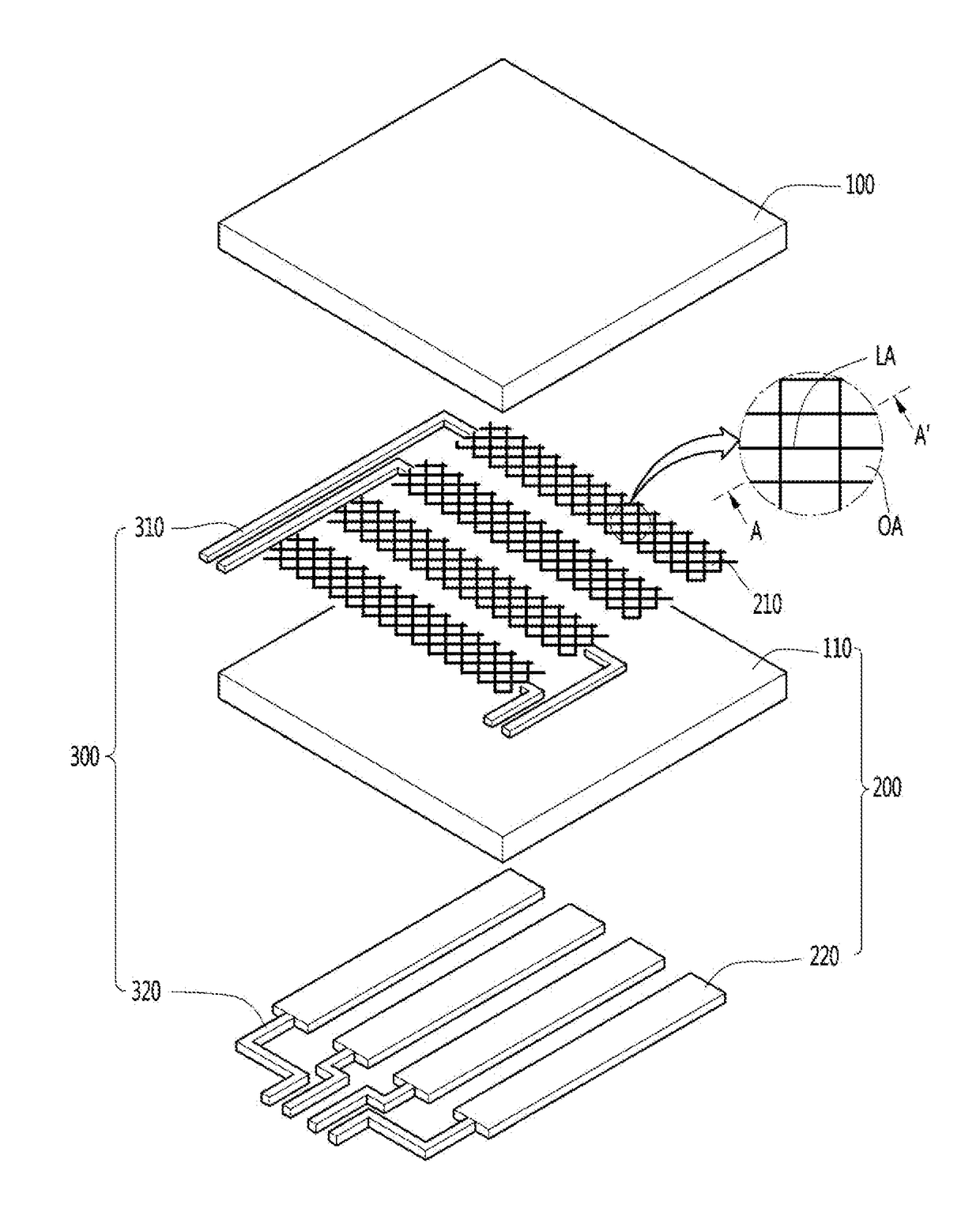
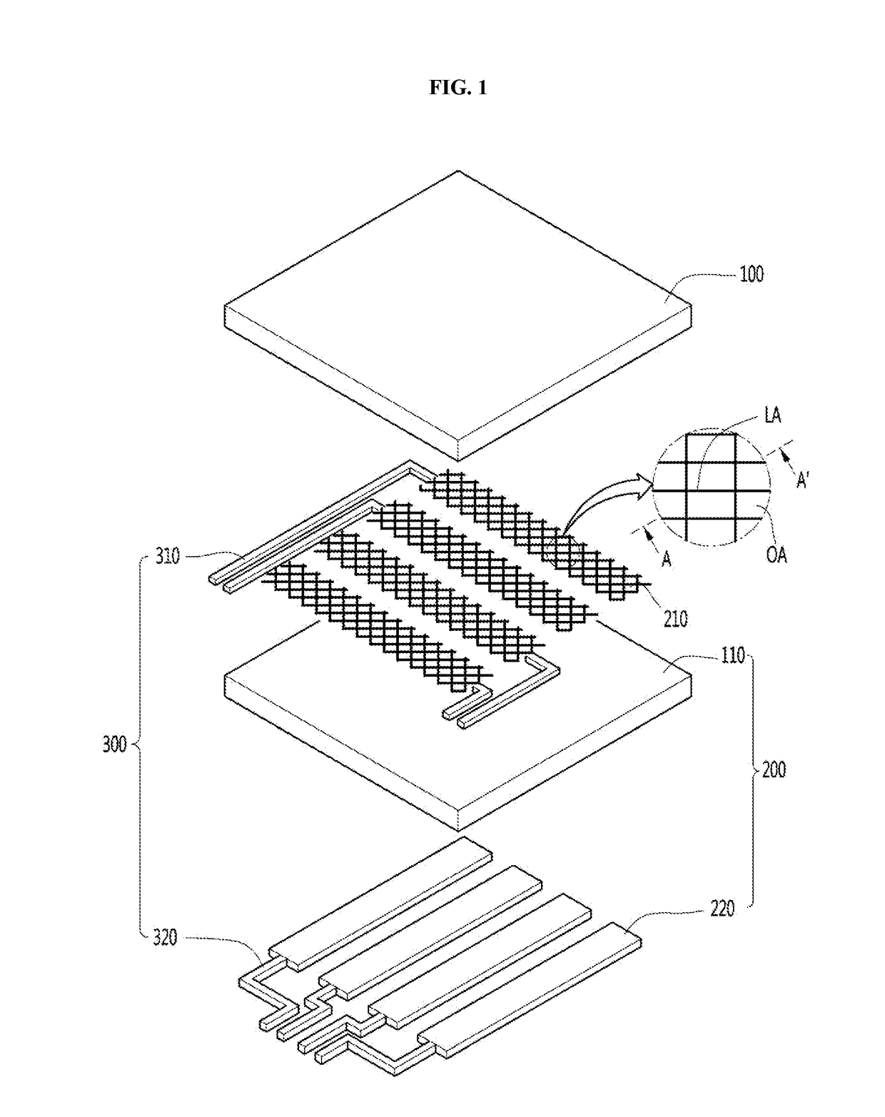
[0041]Referring to FIG. 1, a touch window according to a first embodiment may include a cover substrate 100, a substrate 110, a sensing electrode 200, and a wired electrode 300.

[0042]The cover substrate 100 may be rigid or flexible.

[0043]For example, the cover substrate 100 may include glass or plastic.

[0044]In detail, the cover substrate 100 may include chemically reinforced or heat-strengthened glass such as soda lime glass or aluminosilicate glass, reinforced or flexible plastic such as polyimide (PI), polyethylene terephthalate (PET), propylene glycol (PPG), polycarbonate (PC), and the like, or sapphire.

[0045]Also, the cover substrate 100 may include an optically isotropic film. For example, the cover substrate 100 may include cyclic olefin copolymer (COC), a cyclic olefin polymer (COP), an optically isotropic polycarbonate (PC), or an optically isotropic polymethyl methacrylate (PMMA).

[0046]The sapphire has excellent...

second embodiment

[0132]Referring to FIG. 7, in a touch window a first sensing electrode 210 and a second sensing electrode 220 may be respectively disposed on one surface and the other surface of a substrate 110, i.e., both surfaces of the substrate 110. Thus, since all of the first sensing electrode 210 and the second sensing electrode 220 are disposed on one substrate 110, the touch window may be reduced in entire thickness.

[0133]That is, in the touch window according to this embodiment, since an adhesion layer and one substrate are omitted to reduce the entire thickness of the touch window when compared with a structure in which sensing electrodes 210 are respectively disposed on the separate substrates.

[0134]Each of the first and second electrodes 210 and 220 disposed on both surfaces of the substrate 110, i.e., each of the first sensing electrode 210 disposed on one surface of the substrate 110 and / or the second sensing electrode 220 disposed on the other surface of the substrate 110 may have ...

third embodiment

[0190]Referring to FIG. 10, in a touch window a sensing electrode 200, a wired electrode 300, and a printed circuit board 250 may be disposed on a substrate 110. That is, the substrate 110 may be a support substrate.

[0191]The wired electrode 300 may be connected to the sensing electrode 200 to extend to an unavailable area UA and then be connected to the printed circuit board 250 on the unavailable area UA.

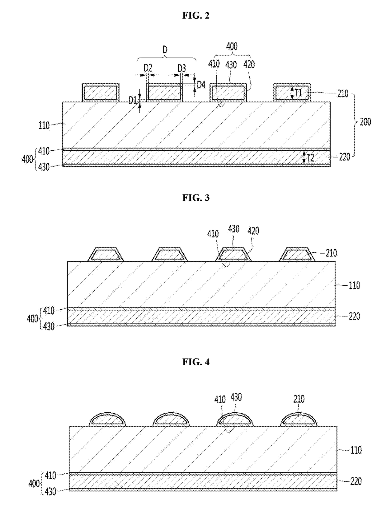
[0192]FIGS. 11 and 13 are cross-sectional views of the touch window according to the third embodiment.

[0193]Referring to FIG. 11, a reflection prevention layer 400 may be disposed on the sensing electrode 200. In detail, the reflection prevention layer 400 may be disposed on at least one surface of one surface and the other surface of the sensing electrode 200. In more detail, the reflection prevention layer 400 may be disposed on each of one surface and the other surface of the sensing electrode 200.

[0194]Referring to FIG. 11, the reflection prevention layer 400 may include a fi...


PUM


Abstract

A touch window according to an embodiment comprises: a substrate; a sensing electrode arranged on the substrate; and a reflection prevention layer arranged on the sensing electrode, wherein the reflection prevention layer comprises a first sub reflection prevention layer arranged on a first surface of the sensing electrode, a third sub reflection prevention layer arranged on a second surface, which lies opposite the first surface, and second sub reflection prevention layers arranged on both side surfaces, which connect the first and second surfaces, respectively. In addition, a touch window according to an embodiment comprises: a substrate; a base member comprising a pattern portion arranged on the substrate; a sensing electrode arranged inside the pattern portion; and a reflection prevention layer surrounding the sensing electrode, wherein the reflection prevention layer comprises a first sub reflection prevention layer arranged on the lower surface of the sensing electrode, second sub reflection prevention layers arranged on both side surfaces of the sensing electrode, and a third sub reflection prevention layer arranged on the upper surface of the sensing electrode, and the second sub reflection prevention layers comprise inclined surfaces, respectively. In addition, a touch window according to an embodiment comprises: a substrate; a sensing electrode on the substrate; a first sub reflection prevention layer arranged on a first surface of the sensing electrode; and a third sub reflection prevention layer arranged on a second surface of the sensing electrode, wherein at least one of the sensing electrode, the first sub reflection prevention layer, and the third sub reflection prevention layer has a side surface inclined at an acute angle of inclination with regard to a surface of the substrate.

Description

CROSS-REFERENCE TO RELATED PATENT APPLICATIONS[0001]This application is a U.S. National Stage Application under 35 U.S.C. § 371 of PCT Application No. PCT / KR2016 / 003740, filed Apr. 8, 2017, which claims priority to Korean Patent Application No. 10-2015-0057916, filed Apr. 24, 2015, Korean Patent Application No. 10-2015-0091165, filed Jun. 26, 2015, and Korean Patent Application No. 10-2015-0101911, filed Jul. 17, 2015, whose entire disclosures are hereby incorporated by reference.TECHNICAL FIELD[0002]In recent, touch windows are being applied to various electronics in a manner in which an input device such as a finger or stylus comes into contact with an image displayed on a display device to perform an input operation.BACKGROUND ART[0003]In such a touch window, a sensing electrode and a wired electrode connected to the sensing electrode are disposed on a substrate.[0004]When an area on which the sensing electrode is disposed is touched, a variation in capacitance may be sensed to d...

Claims


Application Information

Patent Timeline
Patent Type & Authority Applications(United States)
IPC IPC(8): G06F3/044G06F3/047
CPCG06F3/044G06F3/047G06F2203/04112G06F3/0412G06F2203/04102G06F3/0445G06F3/0446G06F3/041
Inventor CHO, SUNG OHKWEON, SEONG ILLEE, DONG KEONKIM, WONG SICKIM, JA RAMSEONG, DONG MUGLEE, SUK YONG
Owner LG INNOTEK CO LTD
Why Eureka
Try Eureka