Eureka AIR delivers breakthrough ideas for toughest innovation challenges, trusted by R&D personnel around the world.

Diffuser plate

a technology of diffusing plate and diffuser, which is applied in the field of diffusing plate, can solve the problems of uneven luminance and color, and achieve the effects of simple structure, low luminance and color unevenness, and good optical properties

Active Publication Date: 2018-04-19
KURARAY CO LTD
View PDF6 Cites 7 Cited by
  • Summary
  • Abstract
  • Description
  • Claims
  • Application Information

AI Technical Summary

Benefits of technology

The present invention provides a diffuser plate that has simple structure and can achieve optical properties with low luminance and color unevenness while producing excellent appearance quality when projecting images.

Problems solved by technology

When only one microlens array is used, unevenness in luminance and color is likely to occur.

Method used


Image

  • Diffuser plate
  • Diffuser plate
  • Diffuser plate

Examples


first embodiment

[0057]Hereinafter, embodiments of the present disclosure will be described with reference to the drawings.

(Shape of Diffuser Plate)

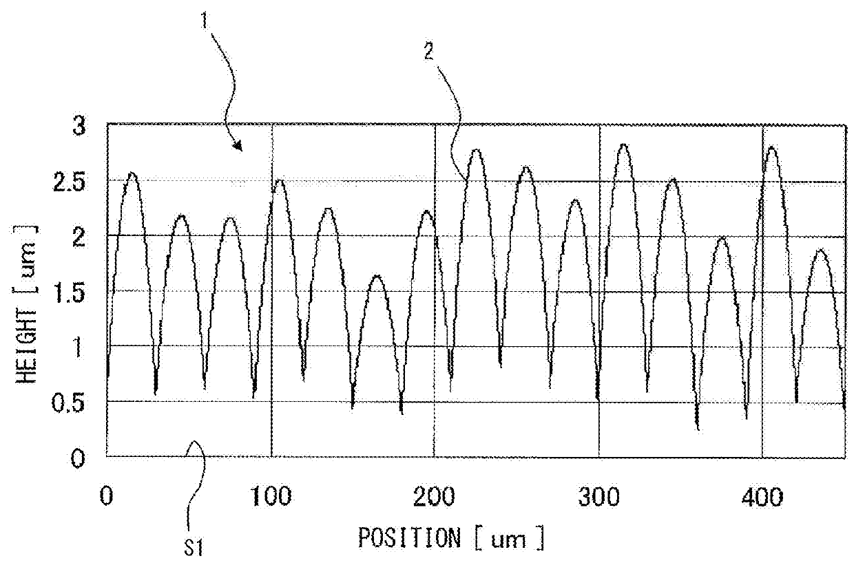
[0058]FIG. 1 is a diagram showing a cross-sectional profile of a cross section of a diffuser plate 1 perpendicular to a main surface S1 according to this embodiment. As shown in FIG. 1, the diffuser plate 1 is a light diffuser plate in which a plurality of microlenses 2 are arranged on the main surface S1 of the substrate. The plurality of microlenses 2 are arranged in a lattice pattern on the main surface S1. The vertical axis of FIG. 1 represents the heights of the lenses from the main surface S1 shape when the height of the main surface S1 of the substrate is 0. The horizontal axis of FIG. 1 represents the positions of the lenses in the direction parallel to the main surface S1. Note that an optical axis of the microlens array composed of the plurality of microlenses 2 is oriented in a direction perpendicular to the main surface S1.

[0059]As shown in F...

examples

[0120]Hereinafter, the present disclosure will be described in more detail based on examples of the diffuser plate 1 according to this embodiment.

[0121]As described above, in the diffuser plate 1 of this embodiment, the microlens array composed of the plurality of microlenses 2 on the main surface S1 was designed by dividing it into the phase modulation shape 4 and the plurality of reference microlenses 3.

[0122]The phase modulation shape 4 was configured for the entire microlens array. In the phase modulation shape 4, the maximum height difference from the main surface S1 for giving the phase differences was ΔH=1.5 μm. On the main surface S1, uniform random numbers corresponding to respective positions of the plurality of microlenses 2 were generated to set raised heights (raised parts) for giving the phase differences. However, when different raised heights were set for the plurality of respective microlenses 2, the phase differences in the adjacent microlenses 2 become discontinuo...


PUM


Abstract

A diffuser plate includes a plurality of fine structures having two or more types of lens functions arranged on a main surface. Intensity of diffused light within a desired diffusion angle range is substantially uniform, and the diffuser plate satisfies a relation of P×P×Sk≤400 [μm2], where P is an average pitch of the plurality of fine structures, Sk is a standard deviation of relative luminance of the plurality of fine structures in their front directions, P≤200 [μm], and Sk≥0.005. Thus, it is possible to provide a diffuser plate having a simple structure capable of achieving optical properties with little luminance and color unevenness and excellent appearance quality when an image is projected.

Description

TECHNICAL FIELD[0001]The present disclosure relates to a diffuser plate.BACKGROUND ART[0002]A diffuser plate using a microlens array is used as a screen for head-up displays and laser projectors. An advantage of using the microlens array is that speckle noise in a laser beam can be reduced more than when a diffuser plate such as a translucent plate or ground glass is used.[0003]Patent Literature 1 discloses an image forming apparatus including a diffuser plate. The diffuser plate uses a laser beam as a light source and includes a laser projector that projects an image formed by an arrangement of a plurality of pixels and a microlens array in which a plurality of microlenses are arranged. When a microlens array is used, incident light can be appropriately diffused, and a necessary diffusion angle can be freely designed.[0004]Patent Literature 2 and 3 and Non Patent Literature 1 disclose a screen using two microlens arrays. When only one microlens array is used, unevenness in luminanc...

Claims


Application Information

Patent Timeline
Patent Type & Authority Applications(United States)
IPC IPC(8): G02B3/00G02B5/02G02B27/48G02B27/01
CPCG02B3/0043G02B5/0278G02B5/0221G02B27/48G02B27/0101G02B2027/013G02B5/0215G02B5/0284G02B3/0056G02B3/0006G02B5/021G02B27/01G02B5/02G02B3/00
Inventor UCHIDA, ATSUSHIKARAI, MASARUWATANABE
Owner KURARAY CO LTD
Why Eureka
Eureka Blog
Learn More