Unlock instant, AI-driven research and patent intelligence for your innovation.

Switching power supply

Active Publication Date: 2018-04-19
FUJI ELECTRIC CO LTD
View PDF6 Cites 4 Cited by
  • Summary
  • Abstract
  • Description
  • Claims
  • Application Information

AI Technical Summary

Benefits of technology

The present invention is a switching power supply that aims to reduce switching loss, increase power conversion efficiency, and lower power consumption. It uses the characteristics of SiC MOSFETs to make the most of its performance under heavy load while still maintaining a simple configuration. The control circuit includes a switching frequency control unit that can adjust the switching frequency of the main and secondary switching devices based on the power consumption of the load. This allows for efficient power conversion and reduced switching loss under light load. The invention also takes advantage of the voltage of the output voltage to further increase power conversion efficiency under heavy load. Overall, the present invention has a simple configuration and effective utilization of SiC MOSFETs to achieve efficient power conversion and reduced energy consumption.

Problems solved by technology

As described above, conventional approaches for reducing loss in switching power supplies 1 while in standby mode include switching frequency fsw reduction control as well as intermittent burst switching control of the switching device Q. However, if a high-power FET that satisfies the desired power capacity rating for the switching power supply 1 is used for the switching device Q, the switching loss in the FET while in standby mode cannot be ignored.

Method used


Image

  • Switching power supply
  • Switching power supply
  • Switching power supply

Examples


Embodiment Construction

[0055]Next, switching power supplies according to embodiments of the present invention will be described with reference to figures. The present invention is suitable for application to switching power supplies with a rated power capacity of approximately several dozen watts, for example.

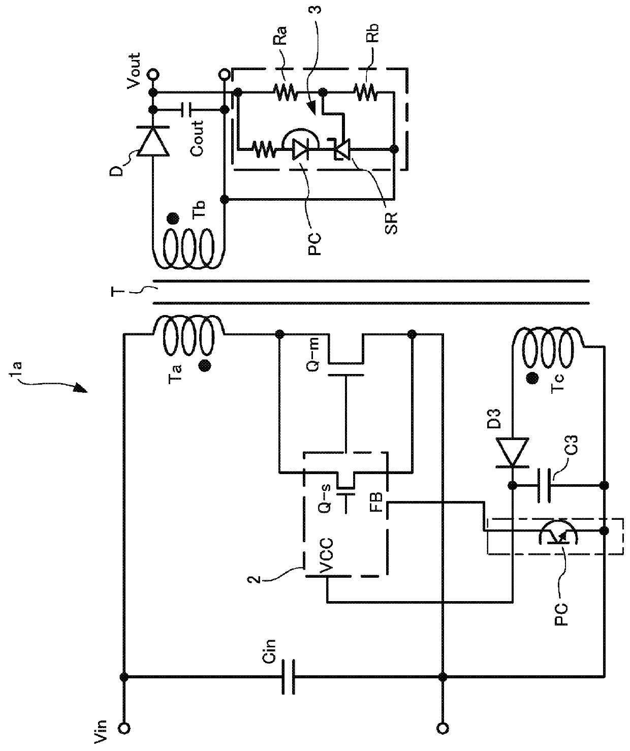
[0056]A switching power supply 1a according to an embodiment of the present invention is a secondary-side regulated flyback DC-DC converter, for example. This flyback DC-DC converter has substantially the same configuration as was described in reference to FIG. 5. Therefore, here the same reference characters will be used for components that are the same as in the switching power supply 1 illustrated in FIG. 5.

[0057]FIG. 1 schematically illustrates a configuration of the main components of the switching power supply 1a according to the present embodiment. The switching power supply 1a includes, as switching devices Q that are connected in series to a primary coil Ta of a transformer T, a main switchi...


PUM


Abstract

A switching power supply includes a SiC MOSFET (a main switching device) that switches a main current flowing through a primary coil of a transformer ON and OFF as well as a Si MOSFET (a secondary switching device) that has a lower power capacity than the main switching device and is arranged in parallel therewith. A control circuit includes a driver circuit that respectively switches the main switching device and the secondary switching device ON and OFF on the basis of a control signal generated in accordance with an output voltage obtained from a secondary coil of the transformer. The control circuit further includes an enable control circuit that disables the ON / OFF switching of the main switching device when a voltage of an auxiliary voltage obtained from an auxiliary coil of the transformer is less than a prescribed threshold voltage.

Description

BACKGROUND OF THE INVENTIONTechnical Field[0001]The present invention relates to a switching power supply that has a simple configuration and makes it possible to reduce switching loss in a switching device, increase power conversion efficiency while under heavy load, and reduce power consumption while in standby mode.Background Art[0002]One example of a switching power supply 1 having a rated power capacity of approximately several dozen watts is the flyback DC-DC converter illustrated in FIG. 5. This switching power supply 1 includes a diode bridge circuit DB that full-wave rectifies AC power supplied from a commercial 100V or 220V AC power source on the input side as well as an input capacitor Cin that smooths the output from the diode bridge circuit DB.[0003]Moreover, as illustrated in FIG. 5, first and second noise filters NF1 and NF2 as well as a capacitor Cx are arranged on an AC power input line that is upstream of the diode bridge circuit DB. Furthermore, a resistor Rx is c...

Claims


Application Information

Patent Timeline
IPC IPC(8): H02M1/08H02M3/335
CPCH02M1/08H02M3/33569H02M2001/0054H02M2001/0032Y02B70/10H02M1/0054H02M1/0032H02M3/33571H02M3/01H02M1/088
Inventor NISHIJIMA, KENICHI
Owner FUJI ELECTRIC CO LTD