Superconducting coil configuration

a superconducting coil and configuration technology, applied in the field of superconducting coil configuration, can solve the problems of affecting the operation of the magnet itself, strands may be particularly susceptible to damage, adversely affecting critical current, etc., and achieves the effects of enhancing stability, current capacity, and enhancing current capacity

Pending Publication Date: 2018-05-03
MEVION MEDICAL SYST
View PDF13 Cites 1 Cited by
  • Summary
  • Abstract
  • Description
  • Claims
  • Application Information

AI Technical Summary

Benefits of technology

[0034]As shown in the table above, the known four-superconducting-strand implementation actually has a larger cross-sectional superconducting area than the example six-superconducting-strand implementation. Consequently, the known four-superconducting-strand implementation may have greater current-carrying capacity than the example six-superconducting-strand implementation (for coils having about the same cross-sectional area). However, the example six-superconducting-strand implementation has advantages, as described herein, in terms of stability and operational reliability. The example seven-superconducting-strand implementation has a larger cross-sectional superconducting area than the known four-superconducting-strand implementation and thus may have greater current-carrying capacity than the known four-superconducting-strand implementation (for conductors having about the same cross-sectional area).
[0035]As explained above, the integrated conductors described herein are wound to produce a superconducting coil. The benefits described for the different integrated conductors inure to the superconducting coil produced therefrom. That is, because a superconducting coil is formed by winding multiple integrated conductors, the enhanced stability, reliability, current capacity, or other benefits of the integrated conductors also apply to the resulting superconducting coil.
[0036]Superconducting coil implementations described herein may be used in a superconducting magnet. For example, for an integrated conductor having a six-strand configuration, each superconducting strand may be configured to support a critical current of 557 Amperes (A) at operating conditions of about 4.2° K and about 11 Tesla (T) magnetic field. For a six-strand implementation having current carrying capacity of 2000 A, each strand carries about 333 A. For a six-strand implementation having current carrying capacity of 3000 A, each strand carries about 500 A. An example seven-superconducting-strand implementation may improve the electromagnetic performance of the magnet for reasons described herein. Referring to the table above, a lower hot spot temperature during a magnet quench implies that the six-superconducting-strand implementation is thermally more stable. On the other hand, a magnet wound with a coil that employs the seven-superconducting-strand implementation may operate at a lower fraction of the critical current.

Problems solved by technology

Defects in one or more of the superconducting strands can adversely affect critical current (maximum superconductor current at given temperature and (B) field).
In some cases, this can affect the operation of the magnet itself.
The strands may be particularly susceptible to damage at thin points in a strand.
As a result, current flows through the superconductor substantially unimpeded.
As a result, when the coil is below the threshold temperature, only the outer strands can achieve superconductivity, but the core cannot.
Accordingly, in such implementations, the integrated conductor includes seven strands that are capable of superconductivity, which may result in an overall increase in a cross-sectional superconducting area of the coil.

Method used


Image

  • Superconducting coil configuration
  • Superconducting coil configuration
  • Superconducting coil configuration

Examples


Embodiment Construction

[0022]In general, a superconductor is an element or metallic alloy which, when cooled below a threshold temperature, loses most, if not all, electrical resistance. As a result, current flows through the superconductor substantially unimpeded. Superconducting coils, therefore, are capable of conducting much larger current than ordinary wires of the same size. Because of the high amounts of current that they are capable of conducting, superconducting coils are particularly useful in electromagnetic applications. However, the superconducting coils described herein are not limited to use in electromagnetic applications, and may be used in any appropriate context.

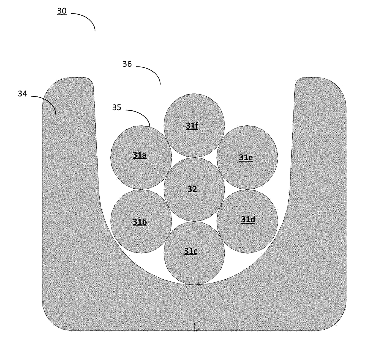
[0023]An example superconducting coil is formed by winding integrated conductors to produce a coil having an appropriate size. A cross-section of an example superconducting coil 24 comprised of multiple wound integrated conductors and positioned against a reverse bobbin 25 is shown in FIG. 3. In some implementations, each integr...


PUM

PropertyMeasurementUnit
diameteraaaaaaaaaa
diameteraaaaaaaaaa
diameteraaaaaaaaaa

Abstract

An example particle therapy system includes: a synchrocyclotron, and a gantry on which the synchrocyclotron is mounted to rotate around a patient position to position the synchrocyclotron relative to a treatment area of the patient. The synchrocyclotron includes a magnet having a coil to receive electrical current and to generate a magnetic field in response to the electrical current. The magnetic field causes the particles to move orbitally within a cavity at an energy that corresponds to the electrical current, and the coil includes multiple integrated conductors that are wound together. An integrated conductor includes: a core including conductive or superconducting material; and at least six strands wound around the core, with each of the at least six strands including a superconducting material. The synchrocyclotron includes an extraction channel to receive the particles from the cavity and to output the particles received from the cavity.

Description

TECHNICAL FIELD[0001]This disclosure relates generally to a superconducting coil configuration.BACKGROUND[0002]A superconducting magnet generates a magnetic field by passing current through one or more superconducting coils. A known superconducting coil configuration includes, in each integrated conductor, four superconducting strands made from niobium-tin (Nb3Sn) wound around a non-superconducting copper (Cu) center strand. In the known superconducting coil configuration, each superconducting strand has a diameter of about 0.8 millimeters (mm), and the center strand has a diameter of about 0.33 mm. An example of the known four-superconducting-strand implementation 5 is shown in FIG. 1.[0003]Defects in one or more of the superconducting strands can adversely affect critical current (maximum superconductor current at given temperature and (B) field). In some cases, this can affect the operation of the magnet itself. Such defects may include, but are not limited to, breakage or cracks...

Claims


Application Information

Patent Timeline
Patent Type & Authority Applications(United States)
IPC IPC(8): H01F6/06A61N5/10
CPCH01F6/06A61N2005/1087A61N5/1081H10N60/20
Inventor SOBCZYNSKI, STANISLAW P.AIZED, DAWOOD
Owner MEVION MEDICAL SYST
Why Eureka
Try Eureka