Film-covered battery

Active Publication Date: 2018-05-03
NEC ENERGY DEVICES LTD
View PDF1 Cites 2 Cited by
  • Summary
  • Abstract
  • Description
  • Claims
  • Application Information

AI Technical Summary

Benefits of technology

[0014]In the present invention, the interface bonding portion is formed so as to be adjacent to the battery element side of the agglomeration/sealing portion which is formed at least a part of the sealing portion of the film covering material. Thus, when the film-covered battery bulges due to generation of gas inside the battery, the sealing portion is cleave

Problems solved by technology

When a gas is generated inside the battery having the structure as disclosed in Patent Document 1 due to repetition of charge and discharge or due to use under a high-temperature environment, the following problems occur.
Then, contact between the

Method used


Image

  • Film-covered battery
  • Film-covered battery
  • Film-covered battery

Examples


example 1

(Production of Positive Electrode)

[0075]92 parts by mass of manganese lithium (LiMn2O4) powder, 5 parts by mass of carbon black, and 3 parts by mass of polyvinylidene fluoride were kneaded with NMP to prepare a positive electrode slurry. The obtained positive electrode slurry was coated on both side surfaces of a 20 μm thickness aluminum foil and then dried, followed by pressing of a positive electrode surface by a roll.

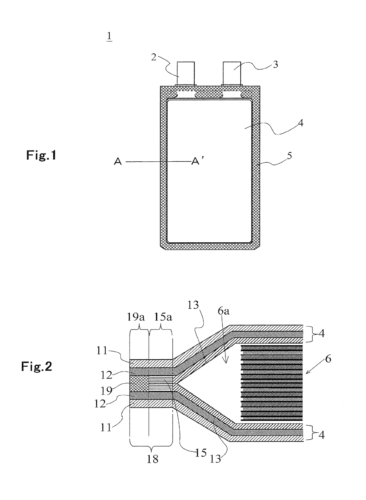
[0076]Then, the aluminum foil coated with a positive electrode active material was cut to obtain a positive electrode in which a positive electrode with 105 mm length and 55 mm width and a positive electrode tab with 15 mm length and 10 mm width is integrally formed.

(Production of Negative Electrode)

[0077]91 parts by mass of graphite, 1 part by mass of carbon black, and 8 parts by mass of polyvinylidene fluoride were kneaded with NMP to prepare a negative electrode slurry. The obtained negative electrode slurry was coated on both side surfaces of a 10 μm thickness co...

example 2

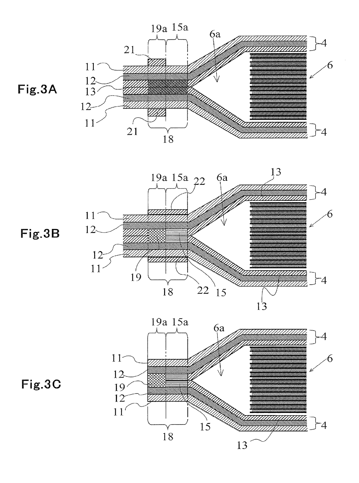
[0099]One of the two heating members in Example 1 was disposed such that the end face thereof on the embossed portion side is separated by 0.5 mm from the boundary between the embossed portion of the film covering material and flat portion, and the other one thereof was disposed such that the end face thereof on the embossed portion side is separated by 0.6 mm from the boundary between the embossed portion of the film covering material and flat portion thereof toward the flat portion side, followed by sealing.

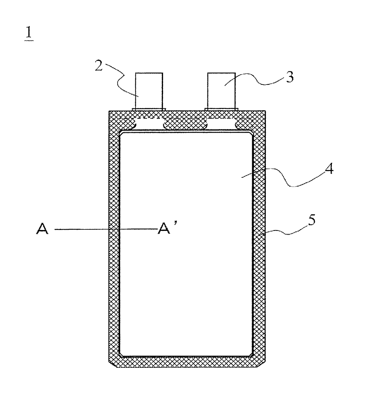
[0100]The film-covered battery was produced with other conditions being the same as those in Example 1. As a result, a film-covered battery having a cross sectional structure illustrated in FIG. 4 was obtained.

[0101]By slightly displacing the two heating members that sandwiching the film covering material, a displacement is generated in a position where the heat sealing layer of the sealing portion is softened.

[0102]As a result, the heat sealing layer of the film covering mater...

example 3

[0104]The heating members used in Example 1 were each disposed such that the end face thereof on the embossed portion side is separated by 0.3 mm from the boundary between the embossed portion of the film covering material and flat portion thereof toward the flat portion side. The film-covered battery was produced with other conditions being the same as those in Example 1. As a result, a film-covered battery having a cross sectional structure illustrated in FIG. 5 was obtained.

[0105]That is, the end face of the heating member is separated by 0.3 mm from the boundary between the embossed portion of the film-shaped covering material and flat portion thereof toward the flat portion side, followed by sealing.

[0106]As a result, the heat sealing layer protrudes inward from the sealing portion to form the resin mass 32.

[0107]The deterioration acceleration test was performed for the battery produced in Example 3 in the same manner as for the battery of Example 1, and results thereof are sho...


PUM

PropertyMeasurementUnit
Lengthaaaaaaaaaa
Lengthaaaaaaaaaa
Lengthaaaaaaaaaa

Abstract

A film-covered battery houses, in a film covering material 4 obtained by stacking a heat sealing layer 13, a barrier layer 12, and a protective layer 11, a battery element 6 obtained by arranging positive and negative electrodes through separators and has a sealing portion that seals a periphery of the film covering material 4 housing the battery element 6. The sealing portion 18 includes an agglomeration/sealing portion 19 and a first interface bonding portion 15 provided so as to be adjacent to the battery element housing portion side of the agglomeration/sealing portion.

Description

CROSS REFERENCE TO RELATED APPLICATIONS[0001]This application is a Continuation of U.S. application Ser. No. 14 / 411,237, filed Dec. 24, 2014, which is a National Stage of International Application No. PCT / JP2013-066569, filed Jun. 17, 2013, claiming priority based on Japanese Patent Application No. 2012-136721, filed Jun. 18, 2012, the contents of all which are incorporated herein by reference in their entirety.TECHNICAL FIELD[0002]The present invention relates to a battery in which a battery element is housed in a film covering material and a manufacturing method thereof and, more particularly, to a film-covered battery having high long-term reliability and a manufacturing method therefore.BACKGROUND ART[0003]A lithium-ion battery having a high capacity density and a high mass density is mounted not only on a mobile device such a mobile phone or a digital camera but also on an electric bicycle, an electric motor cycle, an electric vehicle, and the like. Further, with diversificatio...

Claims


Application Information

Patent Timeline
IPC IPC(8): H01M2/02H01M10/0525H01M2/08H01M50/105H01M50/126H01M50/131H01M50/145H01M50/186
CPCH01M10/0525H01M2220/20H01M2220/30H01M2/0287H01M2/0275H01M2/08H01M2/0237H01M2/0277H01M2/0285Y10T29/49112H01M2/0202H01M50/124H01M50/145H01M50/186H01M50/131H01M50/105H01M50/126Y02E60/10
Inventor ICHIKAWA, TOMOYUKIKOJIMA, IKUO
Owner NEC ENERGY DEVICES LTD
Why Eureka
Try Eureka