
Sun filter for spacecraft

a technology for spacecraft and filters, applied in the direction of transmission, free-space transmission, cosmonautic components, etc., can solve the problems of large thermal load, inability to heat transfer by convection, and high temperature fluctuations within objects, so as to reduce or eliminate unwanted loss or induction of thermal radiation, the effect of reducing a temperature gradien

Active Publication Date: 2018-05-10
TESAT SPACECOM
View PDF0 Cites 3 Cited by
  • Summary
  • Abstract
  • Description
  • Claims
  • Application Information

AI Technical Summary

Benefits of technology

The invention is a device used for optical data transmission that reduces temperatureG gradients and unwanted heating or cooling of components. The device includes a partially transparent surface and a retroreflective surface that directs signal carriers while preventing thermal radiation from taking the same path. This reduces loss of thermal energy and fluctuations in temperature. The device also includes a sending and receiving unit for transmitting and receiving laser radiation. The device helps prevent the loss of thermal energy and reduces the impact of thermal radiation on the spacecraft and components.

Problems solved by technology

Dealing with thermal load may be a major challenge, in particular in connection with spacecraft that are used and operated out of the earth's atmosphere.
Out of the earth's atmosphere, i.e., in vacuum, heat transport by convection is not possible due to lack of atmosphere.
The present or missing or varying irradiation of an object by radiating sources, in particular also by the sun, may result in very high fluctuations in temperature within the object.
This establishes a big challenge for man-made spacecraft, in particular as the used components need to be specified for a limited temperature range.

Method used


Image

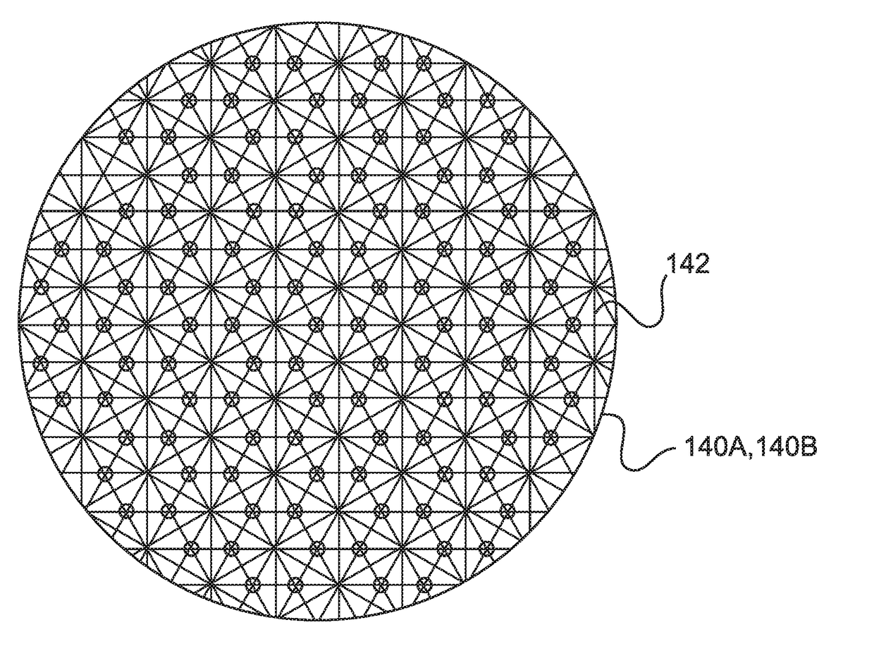
  • Sun filter for spacecraft
  • Sun filter for spacecraft
  • Sun filter for spacecraft

Examples


Embodiment Construction

[0067]The following detailed description is merely illustrative in nature and is not intended to limit the embodiments of the subject matter or the application and uses of such embodiments. As used herein, the word “exemplary” means “serving as an example, instance, or illustration.” Any implementation described herein as exemplary is not necessarily to be construed as preferred or advantageous over other implementations. Furthermore, there is no intention to be bound by any expressed or implied theory presented in the preceding technical field, background, brief summary or the following detailed description.

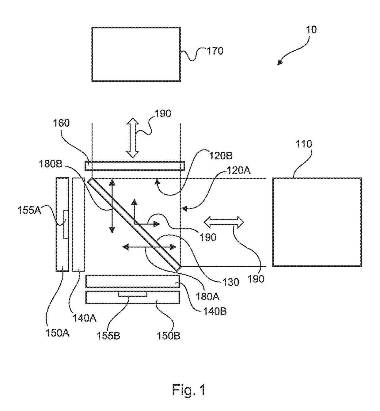
[0068]FIG. 1 shows a device 10 for a sending and receiving unit of a communication arrangement. The device comprises: a first passage 120A for electromagnetic waves and a second passage 120B for electromagnetic waves, a partially transparent surface 130 which is designed transparent for electromagnetic waves of a first wave length range 180A, 180B and which is designed reflectiv...


PUM


Abstract

A device for a sending and receiving unit of a communication arrangement is provided. The device includes: a first passage for electromagnetic waves and a second passage for electromagnetic waves; a partially transparent surface which is transparent for electromagnetic waves of a first wave length range and which is reflective for electromagnetic waves of a second wave length range, wherein the second wave length range differs from the first wave length range; and a first retroreflective surface which is retroreflective for electromagnetic waves of the first wave length range. A direction of reflection of the electromagnetic waves of the first wave length range differs from a direction of reflection of the electromagnetic waves of the second wave length range if the electromagnetic waves of the first wave length range as well as the electromagnetic waves of the second wave length range are incoming through the same passage.

Description

CROSS-REFERENCE TO PRIORITY APPLICATION[0001]This application claims the benefit of, and priority to, German patent application number DE 10 2016 121 484.1, filed on Nov. 9, 2016. The content of the referenced application is incorporated by reference herein.TECHNICAL FIELD[0002]The present disclosure relates to a device for a sending and receiving unit of a communication arrangement and to a spacecraft with such a device. In particular, the disclosure relates to improving of thermal load of the thermal flow with regard to the components of such a device as well as with regard to a spacecraft with such a device.BACKGROUND[0003]Dealing with thermal load may be a major challenge, in particular in connection with spacecraft that are used and operated out of the earth's atmosphere. This is because the heat exchange can take place only by heat conduction and thermal radiation due to lack of atmosphere and without convection.[0004]Basically, heat may flow from a place with higher temperatu...

Claims


Application Information

Patent Timeline
IPC IPC(8): G02B5/26G02B5/12G02B5/20H04B10/112H04B10/40B64G1/66B64G1/58B64G1/10
CPCG02B5/26G02B5/12G02B5/208H04B10/1123H04B10/40B64G1/66B64G1/58B64G1/1007H04B10/118B64G1/50G02B5/124G02B5/22G02B5/281G02B27/1006
Inventor PANZLAFF, KONRADBRZOSKA, ANDREJHOLOTA, WOLFGANGSCHWAB, MARTINMUHLNIKEL, GERDFECHTMANN, CARSTEN
Owner TESAT SPACECOM
Learn More