Shutoff device

a technology of shutoff device and current, which is applied in the field of shutoff device, can solve problems such as worse current detection precision, and achieve the effect of suppressing the reduction of detection precision of dc curren

Active Publication Date: 2018-05-10
PANASONIC INTELLECTUAL PROPERTY MANAGEMENT CO LTD
View PDF1 Cites 11 Cited by
  • Summary
  • Abstract
  • Description
  • Claims
  • Application Information

AI Technical Summary

Benefits of technology

[0006]It is an object of the present invention to provide a shutoff device capable of suppressing reduction in detection precision of a DC current.

Problems solved by technology

The detection core being magnetized may make current detection precision worse.

Method used


Image

  • Shutoff device
  • Shutoff device
  • Shutoff device

Examples


embodiment 1

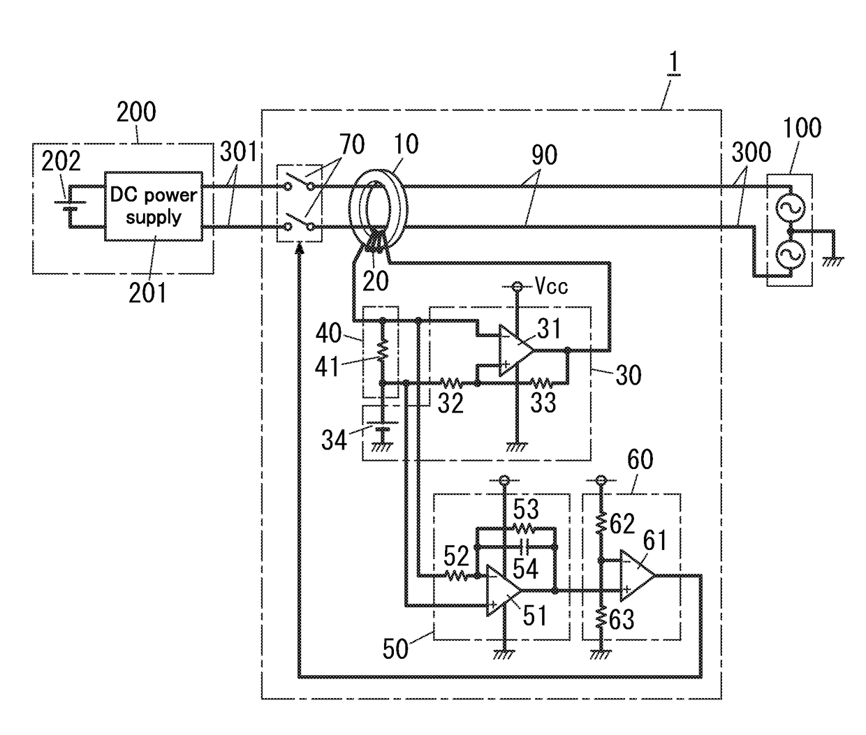
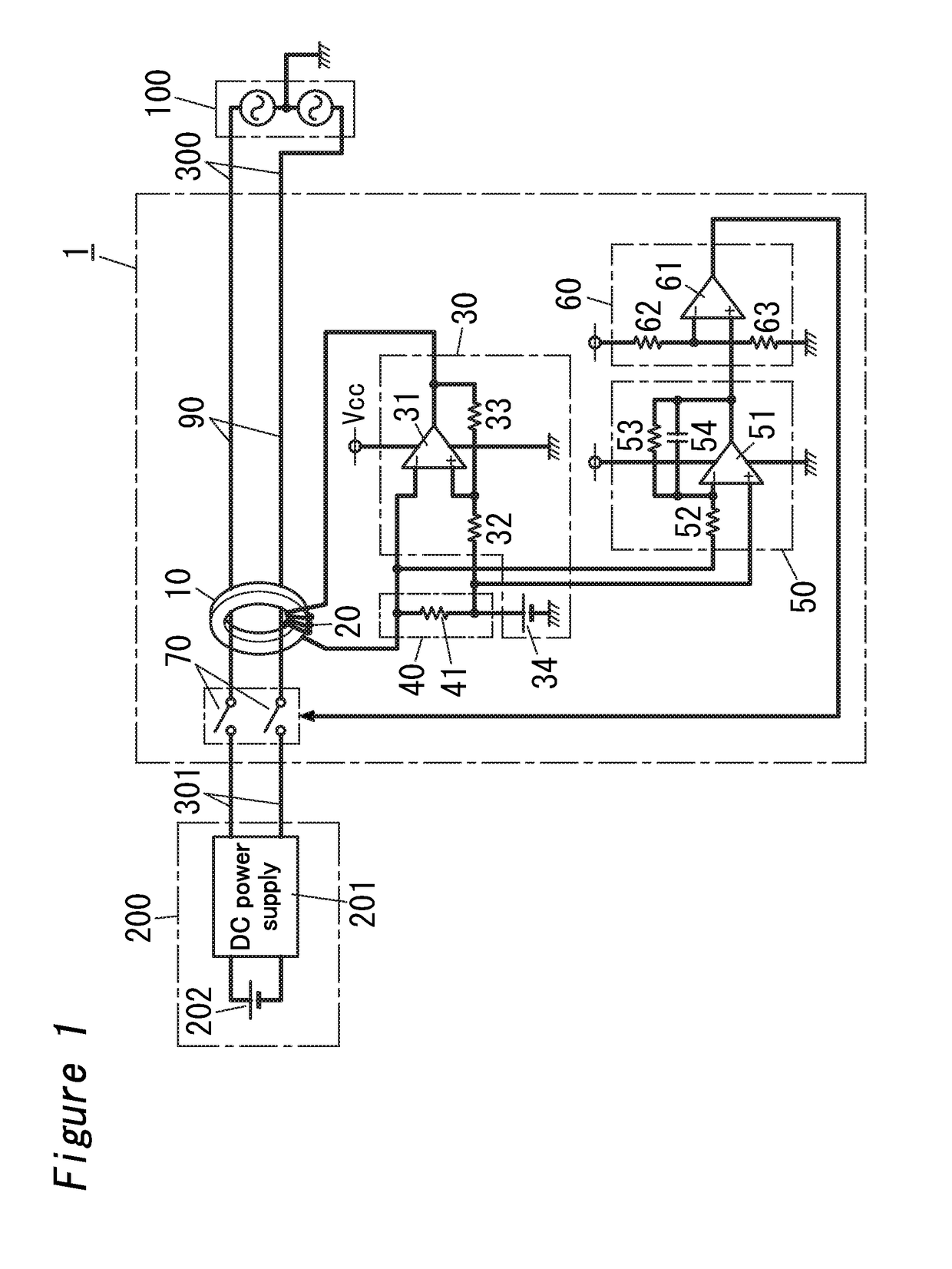
[0014]A shutoff device according to the present embodiment is provided for a charge control device called CCID (Charging Circuit Interrupt Device). The charge control device is provided in a charging cable configured to connect an AC power supply and an electric drive vehicle. Examples of the electric drive vehicle include a hybrid electric vehicle (HEV), a plug-in hybrid electric vehicle (PHEV), an electric vehicle (EV) and the like. The charge control device is configured to interrupt power supply to the electric drive vehicle when detecting a residual current that is a direct current. Note that the application of the shutoff device is not limited to the charge control device, but the shutoff device may also be applied to a charging system. The charging system is system configured to convert AC power from an AC power supply into DC power to charge a storage battery.

[0015]FIG. 1 is a circuit diagram of the shutoff device 1 with which the charge control device is equipped. The shuto...

embodiment 2

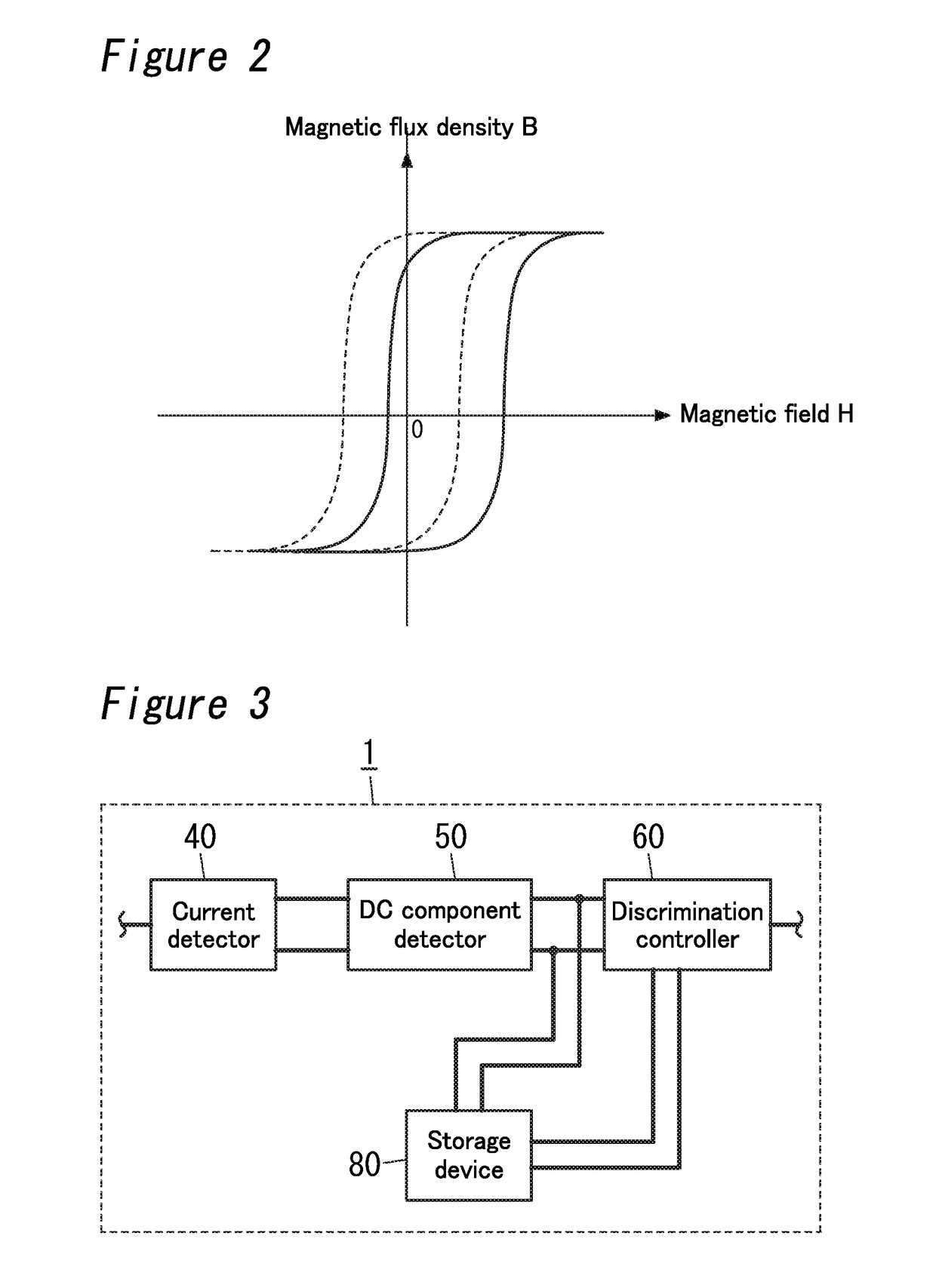
[0037]A shutoff device 1 according to Embodiment 2 will be explained with reference to FIG. 3.

[0038]A shutoff device 1 according to Embodiment 2 includes a storage device 80 in addition to components of the shutoff device 1 according to Embodiment 1. The storage device 80 is configured to store a DC component level detected with a DC component detector 50 when two contact elements 70 are off. Note that since components except for the storage device 80 are similar to those of the shutoff device 1 according to Embodiment 1, like kind components are assigned the same reference numerals as depicted in Embodiment 1, and are not described herein. The organization in the present embodiment can also be applied to Embodiment 3 to be explained below.

[0039]The storage device 80 includes, for example a nonvolatile memory such as EEPROM (Electrically Erasable and Programmable Read Only Memory). The storage device 80 is configured to convert the DC component level detected with the DC component d...

embodiment 3

[0062]A shutoff device 1 according to Embodiment 3 will be explained with reference to FIG. 5.

[0063]In the shutoff device 1 according to Embodiment 3, a current detector 40 corresponding to the shutoff device 1 explained in Embodiment 1 further includes an impedance circuit 400. The impedance circuit 400 is configured to produce a voltage signal that is proportionate to a level of a current flowing through a winding 20. An exciter 30 is configured to supply the winding 20 with an excitation current whose amplitude varies according to a level of the voltage signal produced through the impedance circuit 400. The exciter 30 has an adjuster circuit 35 configured to adjust an impedance value of the impedance circuit 400. Here, when output voltage of the exciter 30 is constant, the amplitude of the excitation current supplied to the winding 20 decreases with an increase in the impedance value of the impedance circuit 400. Note that the configuration except for the impedance circuit 400 an...


PUM


Abstract

A magnetic core is electromagnetically coupled to two conductors that allow an AC current to flow through. An exciter is configured to supply a winding with an excitation current that is an alternating current. A current detector is configured to detect a current flowing through the winding. A DC component detector is configured to detect a DC component level from the current detected with the current detector. Two contact elements are respectively disposed along the two conductors. A discrimination controller is configured to: turn the two contact elements on when the DC component level detected with the DC component detector is less than or equal to a threshold; turn the two contact elements off when the DC component level detected with the DC component detector is greater than the threshold; and turn the two contact elements off in de-energized condition.

Description

TECHNICAL FIELD[0001]The invention relates to shutoff devices and, more particularly, to a shutoff device configured to interrupt power supply.BACKGROUND ART[0002]A conventional photovoltaic system has been provided with photovoltaic cells, a dispersed power supply and a ground fault detector circuit (for example, see Patent Literature 1). The dispersed power supply is configured to convert DC voltage of the photovoltaic cells into AC voltage. The ground fault detector circuit is configured to detect a ground fault in direct current paths connecting the photovoltaic cells and the dispersed power supply.[0003]The ground fault detector circuit includes a zero-phase-sequence current transformer having a detection core through which the direct current paths are threaded, and is configured to detect a ground fault current flowing from an output of a secondary winding wrapped around the detection core through the secondary winding.[0004]With the ground fault detector circuit, there is a p...

Claims


Application Information

Patent Timeline
Patent Type & Authority Applications(United States)
IPC IPC(8): H02H3/16G01R19/165G01R15/18
CPCH02H3/16G01R19/16576G01R19/16571G01R15/183G01R15/04H02H3/006H02H3/332G01R19/0015G01R31/52G01R19/20
Inventor IWAMI, EIJIIKUSHIMA, TSUYOSHIFUKUO, NAOKINISHIGAKI, TOMOKAZU
Owner PANASONIC INTELLECTUAL PROPERTY MANAGEMENT CO LTD
Why Eureka
Try Eureka