
Laser apparatus for cutting brittle material

a technology of brittle material and laser, which is applied in the direction of optical elements, manufacturing tools, instruments, etc., can solve the problems of degrading and weakening the processed material, degrading and weakening the material, and defecting in the transparent brittle material

Active Publication Date: 2018-05-17
COHERENT INC
View PDF5 Cites 21 Cited by
  • Summary
  • Abstract
  • Description
  • Claims
  • Application Information

AI Technical Summary

Benefits of technology

The present invention is about cutting brittle materials using a laser apparatus. The laser apparatus includes a laser-source that produces a collimated beam of pulsed laser-radiation. An aspheric focusing lens is used to focus the beam onto the surface of the material. An afocal beam-expander is placed between the laser-source and the aspheric focusing lens to expand the beam. The focused beam has a uniform intensity distribution along its length and overlaps the material between its entrance and exit surfaces. The technical effect of this invention is that it provides a laser apparatus that can accurately and efficiently cut brittle materials.

Problems solved by technology

Traditional mechanical machining produces unwanted defects, such as micro cracks that may propagate when the processed material is stressed, thereby degrading and weakening the processed material.
Each individual pulse or burst of pulses creates a defect in the transparent brittle material at the focus of the beam.
An array of defects is created by translating the focused beam of pulsed laser-radiation along a cutting path in a workpiece, thereby weakening the material.
One such method is to apply a laser-beam having a wavelength absorbed by the material along the cutting path, which causes mechanical stress through heating.
Larger potassium ions substitute for smaller sodium ions (Na+) located near surfaces of the glass, thereby causing compression within surface-layers in the glass.
Well focused pulsed laser-radiation creates defects that typically extend for a few tens of micrometers in depth.
A phase mask is a type of diffractive optical element (DOE) and is generally rather expensive to fabricate.
Defects created using a Bessel beam may have satellite structure, which can result in a poor quality cut edge.
Relatively small variances in material properties (such as normal material inhomogeneities) and beam parameters (such as shot-to-shot noise and laser-to-laser beam quality) can cause a loss of control in a filament laser-cutting process.

Method used


Image

  • Laser apparatus for cutting brittle material
  • Laser apparatus for cutting brittle material
  • Laser apparatus for cutting brittle material

Examples


Embodiment Construction

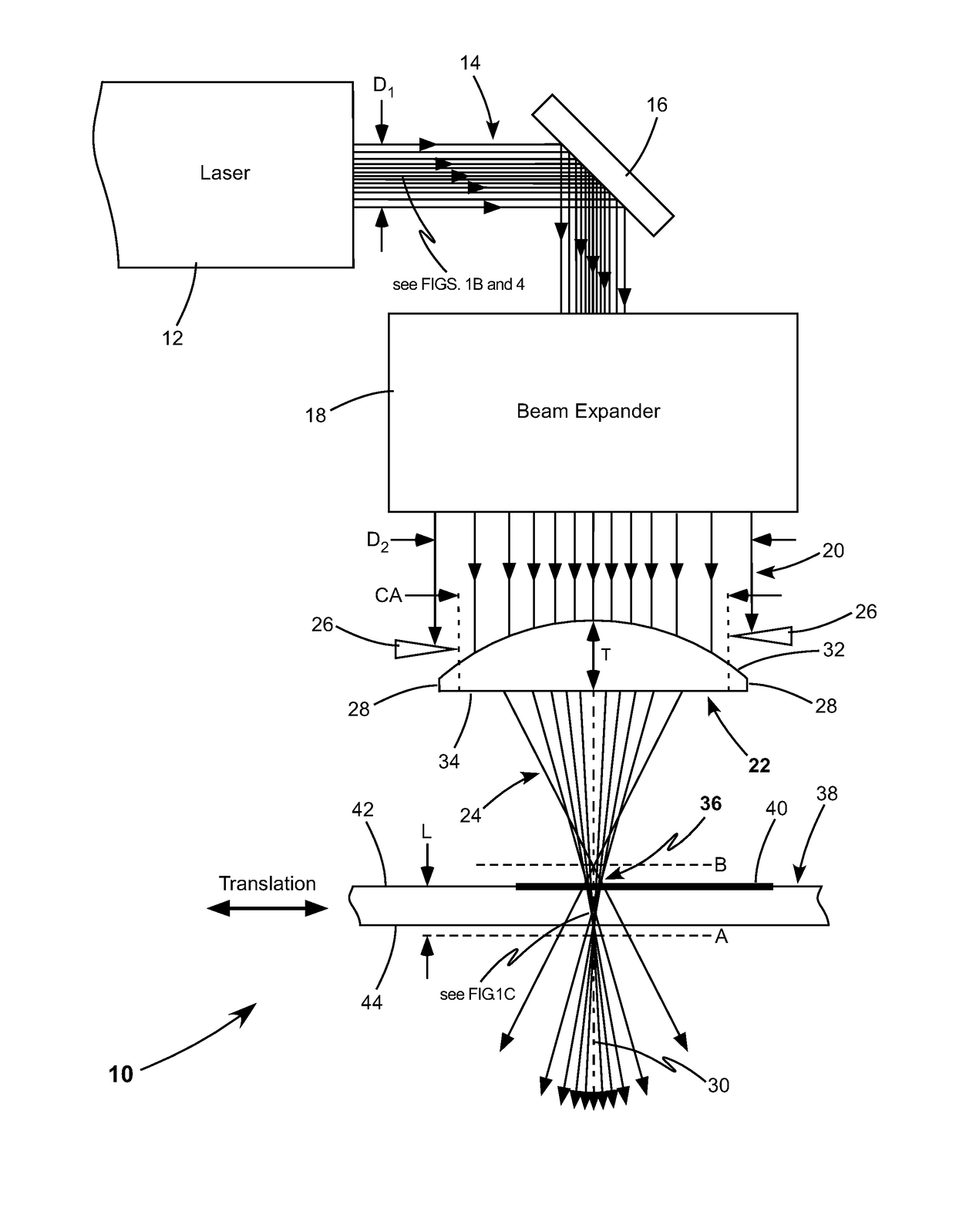
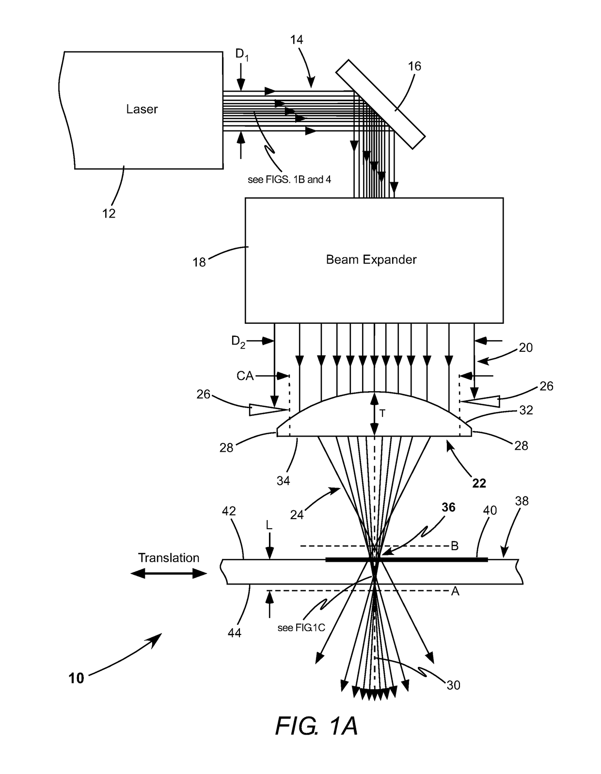
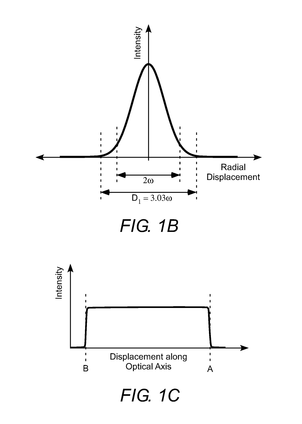
[0024]Referring now to the drawings, wherein like components are designated by like numerals, FIG. 1A schematically illustrates one preferred embodiment 10 of laser-cutting apparatus in accordance with the present invention. Apparatus 10 includes laser-source 12 that delivers a collimated beam of pulsed laser-radiation 14 having a beam-diameter “D1”. Collimated beam 14 is directed by an optional turning mirror 16 into an afocal beam-expander 18, which is arranged to intercept collimated beam 14 and to form an expanded beam of pulsed laser-radiation 20 that is collimated and has a larger beam-diameter “D2”. Afocal beam-expanders are a well-known beam-expanding element in the art of optical design and a description thereof is not necessary for understanding the principles of the present invention.

[0025]An aspheric focusing lens 22 is arranged to intercept expanded collimated beam 20 and form a focused beam of pulsed laser-radiation 24. Beam-diameter D2 is selected to overfill the clea...


PUM

PropertyMeasurementUnit
burst-frequencyaaaaaaaaaa

Abstract

An apparatus for cutting brittle material comprises an aspheric focusing lens, an aperture, and a laser-source generating a beam of pulsed laser-radiation. The aspheric lens and the aperture form the beam of pulsed laser-radiation into an elongated focus having a uniform intensity distribution along the optical axis of the aspheric focusing lens. The elongated focus extends through the full thickness of a workpiece made of a brittle material. The workpiece is cut by tracing the optical axis along a cutting line. Each pulse or burst of pulsed laser-radiation creates an extended defect through the full thickness of the workpiece.

Description

TECHNICAL FIELD OF THE INVENTION[0001]The present invention relates in general to laser machining of transparent brittle materials. The invention relates in particular to cutting glass workpieces using a beam of ultra-short pulsed laser-radiation, having a pulse duration of about 20 picoseconds or less, formed into an elongated focus.DISCUSSION OF BACKGROUND ART[0002]Laser-machining is increasingly used for cutting, drilling, marking, and scribing a wide range of materials, including brittle materials such as glass and sapphire. Traditional mechanical machining produces unwanted defects, such as micro cracks that may propagate when the processed material is stressed, thereby degrading and weakening the processed material. Laser-machining of brittle materials using a focused beam of pulsed laser-radiation produces precise cuts and holes, having high-quality edges and walls, while minimizing the formation of unwanted defects. Industrial progress requires laser-machining of an increasi...

Claims


Application Information

Patent Timeline
Patent Type & Authority Applications(United States)
IPC IPC(8): B23K26/06G02B27/09G02B27/30C03B33/02B23K26/0622B23K26/08B23K26/402
CPCB23K26/0648G02B27/0955G02B27/30B23K2203/54B23K26/0624B23K26/083B23K26/402C03B33/0222B23K26/00B23K26/073C03B33/091B23K26/0626B23K26/702B23K26/0006B23K26/0738B23K26/53B23K26/066B23K2103/54B23K26/38Y02P40/57
Inventor GREENBERG, MICHAEL R.GAUDIOSI, DAVID M.DEILE, JOCHEN
Owner COHERENT INC
Learn More