Metal artifacts reduction for cone beam ct

Active Publication Date: 2018-05-17
CARESTREAM HEALTH INC
View PDF0 Cites 8 Cited by
  • Summary
  • Abstract
  • Description
  • Claims
  • Application Information

AI Technical Summary

Benefits of technology

The patent aims to improve the quality of CBCT volume images by reducing metal artifacts. The invention offers innovative methods to achieve this goal.

Problems solved by technology

Although 3D images of diagnostic quality can be generated using CBCT systems and technology, a number of technical challenges remain.
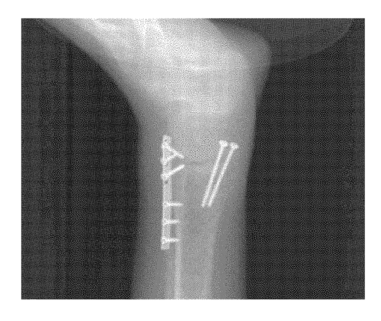
Highly dense objects, such as metallic implants, prostheses and related appliances, surgical clips and staples, dental fillings, and the like can cause various image artifacts that can obscure useful information about the imaged features.
Such artifacts can be due to physical effects such as high quantum noise, radiation scatter, beam hardening, and non-linear amplification in reconstruction algorithms.
These artifacts, generically referred to as metallic artifacts or metal artifacts, can reduce image quality by masking soft tissue structures, not only in the immediate vicinity of the dense object, but also throughout the entire image.
Without some type of compensation, this can falsify CT values and even make it difficult or impossible to use the reconstructed image effectively in assessing patient condition or properly planning radiation therapy or other treatments.
1. Interpolation-based FBP reconstruction approach. This approach operates in the projection domain, where the metal feature or shadow is identified and obscured values are interpolated using nonmetal-contaminated neighbors. For some types of imaging, with a single metal object within a relatively homogeneous volume, this method works acceptably. However, in more complex heterogeneous tissue, particularly where there are multiple metal objects in a heterogeneous volume, the interpolation-based algorithm can make unrealistic assumptions about the volume segment that lies in the shadow of the feature or object(s), leading to prominent errors in the reconstructed images. Theoretically, it is known in the 3D imaging arts that any interpolation-based repair scheme of the Radon space is based on a weak underlying model. Hence, it cannot be expected that the estimated projection data will suitably fit the projection data if measured without metal objects.
2. Iterative reconstruction approach. Generally improved over the performance of interpolation-based FBP described in approach (1), the iterative reconstruction approach is also more successful for severely distorted images. Iterative reconstruction uses some prior knowledge of the image physics, noise properties, and imaging geometry of the system. For this method, it is necessary to have information about the shape and location and, possibly, the attenuation coefficients of the metal objects in the reconstruction image domain. Typically, a constrained optimization approach is applied, which can be very sensitive to system configurations and to the quality of the projection data. These requirements are easily met for computer simulation or phantom imaging, and have been experimentally tested by researchers; however, iterative reconstruction may be impractical for clinical use, where volume geometries are considerably more complex than those used in simulation. Furthermore, iterative reconstruction methods are computationally much more intensive than FBP, making these methods less practical for clinical use in commercial CT scanning apparatus.
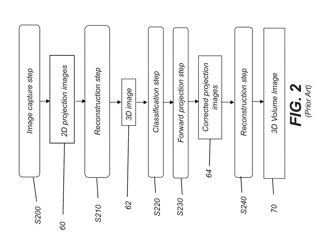
3. Quasi-iterative based FBP approach. The quasi-iterative based FBP approach performs clustering in the reconstruction domain after the initial 3D image reconstruction, without any metal correction or with metal correction introduced in approach (1) (above). The voxel elements of the reconstructed volume are classified into several tissues, such as soft tissue, bone, air, etc., with each voxel assigned a value corresponding to one of these tissue types. This method then forward projects the classified reconstruction volume onto each metal-affected detector element and subsequently generates a final reconstruction of the thus modified raw data to obtain the metal artifacts reduced volume. This method outperforms the interpolation-based FBP approach. The most prominent feature of this method is suppression of secondary artifacts caused by the interpolation scheme. However, one drawback of this method is that it fails whenever the interpolation based approach (1) fails. Moreover, quasi-iterative processing cannot handle the case where the object size exceeds the field of view, since additional artifacts caused by the forward projection are introduced in the corrected images.
It is recognized that metal artifacts reduction is a challenging task, particularly where implant geometries may be more complex.

Method used


Image

  • Metal artifacts reduction for cone beam ct
  • Metal artifacts reduction for cone beam ct
  • Metal artifacts reduction for cone beam ct

Examples


Embodiment Construction

[0036]The following is a detailed description of preferred embodiments of the invention, reference being made to the drawings in which the same reference numerals identify the same elements of structure in each of the several figures. In the drawings and text that follow, like components are designated with like reference numerals, and similar descriptions concerning components and arrangement or interaction of components already described are omitted. Where they are used, the terms “first”, “second”, “third”, and so on, do not necessarily denote any ordinal or priority relation, but are simply used to more clearly distinguish one element from another.

[0037]In the context of the present disclosure, the term “volume image” is synonymous with the terms “3Dimensional image” or “3D image”. Embodiments of the present disclosure are particularly well suited for suppressing the types of metal artifacts that occur in 3D volume images, including cone-beam computed tomography (CBCT) as well a...


PUM


Abstract

A method for processing volume image data obtains two-dimensional projection images of a subject on an image detector, wherein each of the images has the detector and a radiation source at a different scan angles. The image data is arranged as an image stack with corresponding pixel data from the detector in register for each of the images in the stack. A partial subset of projection images showing a metal object is identified. Information relative to the metal object propagates from the partial subject of projection images to the remaining images of the stack. For each of one or more stacked projection images, region growing defines a metal mask and adjusts image data values defined by the mask. The volume image data is reconstructed using region growing results. A 2D image is rendered and displayed from the reconstructed volume image data.

Description

CROSS REFERENCE TO RELATED APPLICATIONS[0001]This application claims the benefit of U.S. Provisional application U.S. Ser. No. 62 / 421,567, provisionally filed on Nov. 14, 2016, entitled “METAL ARTIFACTS REDUCTION FOR CONE BEAM CT”, in the names of Zhang et al., incorporated herein in its entirety.FIELD OF THE INVENTION[0002]The invention relates generally to the field of diagnostic imaging and in particular to Cone-Beam Computed Tomography (CBCT) imaging. More specifically, the invention relates to a method for improving CBCT results using segmentation techniques to reduce metal artifacts in the reconstructed image.BACKGROUND OF THE INVENTION[0003]3D volume imaging is a diagnostic tool that offers significant advantages over earlier 2D radiographic imaging techniques for evaluating the condition of internal structures and organs. 3D imaging of a patient or other subject has been made possible by a number of advancements, including the development of high-speed imaging detectors, suc...

Claims


Application Information

Patent Timeline
IPC IPC(8): G06T11/00G06T7/11G06T7/187G06T7/174G06T7/13
CPCG06T11/008G06T7/11G06T7/187G06T7/174G06T7/13G06T11/006G06T2207/20072G06T2207/20156G06T2207/10081G06T2211/421G06T11/005G06T2200/04
Inventor ZHANG, JINGHUO, ZHIMINZHAO, FRANK
Owner CARESTREAM HEALTH INC
Why Eureka
Try Eureka