Optical system

Active Publication Date: 2018-05-24
KONINKLJIJKE PHILIPS NV
View PDF3 Cites 1 Cited by
  • Summary
  • Abstract
  • Description
  • Claims
  • Application Information

AI Technical Summary

Benefits of technology

The patent describes a device that uses an optical system to reduce skin damage and irritation caused by laser pulses. The device ensures that the lower intensity pulse is the only one that can touch the skin surface. The treatment pulses are also at the same distance from the skin surface as they travel across the recess, which helps to achieve even results. Overall, this device improves performance and produces consistent results.

Problems solved by technology

However, these conventional technologies are harsh on the skin surface and cause damage or irritation.
It is also known that laser beams can themselves cause damage and irritation if the high intensity portion contacts the skin surface.
However, optical systems can become contaminated and the trajectory of the laser beam altered from its intended path.
This can result in the laser beam being directed onto the wrong areas of the skin surface and / or causing damage and irritation to the skin surface.

Method used


Image

  • Optical system
  • Optical system
  • Optical system

Examples


Embodiment Construction

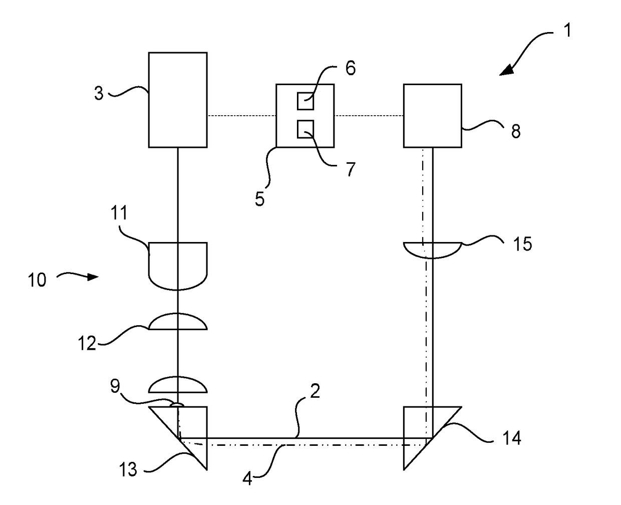
[0047]Referring to FIG. 1, there is shown an optical system 1. The optical system 1 is configured to guide a laser pulse along an intended optical path 2. The intended optical path 2 is the route along which a laser pulse is intended to travel.

[0048]The optical system 1 comprises a laser pulse generating arrangement 3. The laser pulse generating arrangement 3 is configured to generate a treatment pulse and a probe pulse. Therefore, the laser pulse generating arrangement 3 is at the beginning of the intended optical path 2. The laser pulse generating arrangement 3 is configured to direct the laser pulses towards the rest of the optical system 1. The laser pulse generating arrangement 3 may be, for example, but not limited to, a laser diode.

[0049]In the present embodiment, the laser pulse generating arrangement 3 is configured to generate two different laser pulses. The first laser pulse is the probe pulse. The second laser pulse is the treatment pulse. The laser pulse generating arra...


PUM


Abstract

The present application relates to an optical system (1) comprising a plurality of optical components, a pulse generating arrangement (3) configured to generate a treatment pulse along a treatment pulse optical path through said optical components, said pulse generating arrangement also being configured to generate a probe pulse along a probe pulse optical path extending through said optical components, a sensor (8) configured to generate information indicative of an optical characteristic of said probe pulse that has passed along said probe pulse optical path through said optical components, and a controller (5) configured to control said pulse generating apparatus (3) to selectively emit said treatment pulse along said treatment pulse optical path (2), in dependence on the information generated by the sensor (8).

Description

FIELD OF THE INVENTION[0001]The present invention relates to an optical system, in particular, an optical system having a probe pulse to determine the condition of an optical path. The present invention also relates to a laser treatment device comprising the optical system. The present invention further relates to a method for using the laser treatment device.BACKGROUND OF THE INVENTION[0002]Conventional technologies for the treatment of hair and skin include arrangements of mechanical blades and abrasives which are placed against and dragged across a skin surface to cut hair or remove dead skin, respectively. However, these conventional technologies are harsh on the skin surface and cause damage or irritation.[0003]It is known to use a laser beam to sever hair or treat skin as an alternative to mechanical blades and abrasives. Laser beam treatments are preferred because they do not require moving cutting parts or abrasive surfaces to be placed against the skin or hair. Therefore, t...

Claims


Application Information

Patent Timeline
IPC IPC(8): A61B18/20
CPCA61B2018/00476A61B2018/00708A61B2018/00785A61B18/203A61B2018/00452
Inventor MOESKOPS, BASTIAAN WILHELMUS MARIA
Owner KONINKLJIJKE PHILIPS NV
Why Eureka
Try Eureka