Electrode mixture layer

a technology of electrode mixture and mixture layer, applied in the field of electrode mixture layer, can solve the problem of disadvantageous internal resistance and achieve the effect of reducing internal resistance and increasing output values and input values

Active Publication Date: 2018-05-24
HONDA MOTOR CO LTD
View PDF17 Cites 10 Cited by
  • Summary
  • Abstract
  • Description
  • Claims
  • Application Information

AI Technical Summary

Benefits of technology

[0015]The battery of the present invention, in which at least one of the positive electrode-side electrode mixture layer and the negative electrode-side electrode mixture layer is the electrode mixture layer of the present invention, can reduce the internal resistance and can increase output values and input values.

Problems solved by technology

However, an electrode constituted by binding the electrode also serving as a current collector described in Japanese Patent Laid-Open No. 2016-31922 as an electrode mixture layer to a separate current collector disadvantageously has higher internal resistance, in comparison with an electrode constituted by binding an electrode mixture layer composed of a common active material, a conductor, and a binder, to a current collector.

Method used


Image

  • Electrode mixture layer
  • Electrode mixture layer
  • Electrode mixture layer

Examples


example 11

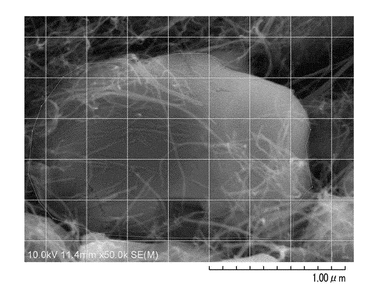
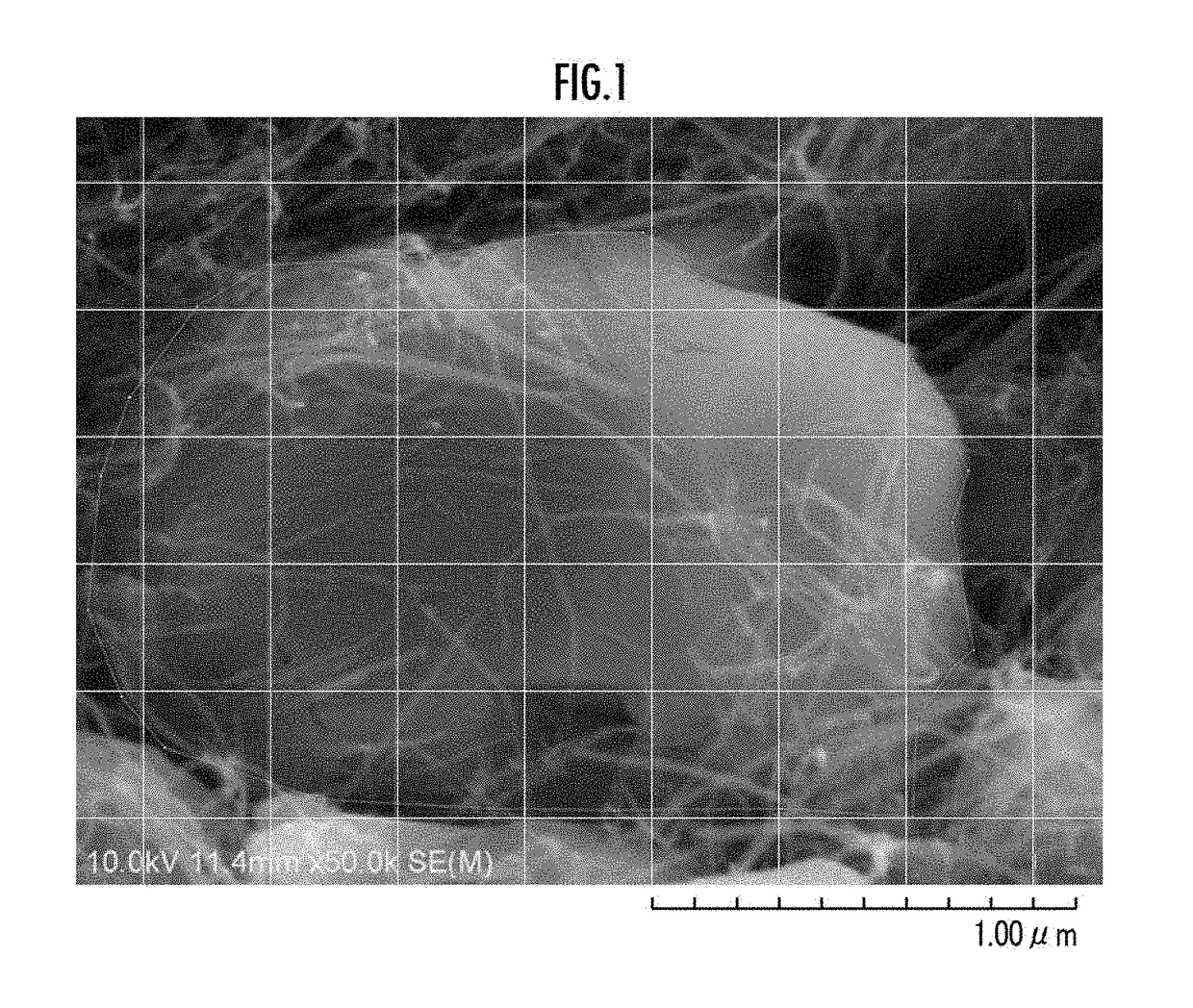
[0026]In the present example, first, 0.7 mg / ml of carbon nanotubes having a diameter of 0.8 to 1.5 nm and a length of 150 μm (manufactured by Meijo Nano Carbon Co., Ltd., product name: EC-15), 7.1 mg / ml of Li(Ni1 / 3Co1 / 3Mn1 / 3)O2 as a positive electrode active material, and 20 mg / ml of dodecyl lithium sulfate as a dispersant were placed in 150 ml of water and treated using an ultrasonic homogenizer at an output of 50 W for 60 minutes to prepare a primary dispersion liquid. In the primary dispersion liquid, the mass ratio between the carbon nanotubes and the positive electrode active material is 9:91.

[0027]The primary dispersion liquid was treated five times by a cross flow from a nozzle diameter of 100 μm and at a pressure of 200 MPa using a wet type atomizer NanoVater® manufactured by YOSHIDA KIKAI CO., LTD. to prepare a secondary dispersion liquid.

[0028]Next, the secondary dispersion liquid was placed in a suction filtration device to deposit a mixture of the carbon nanotubes and th...

example 2

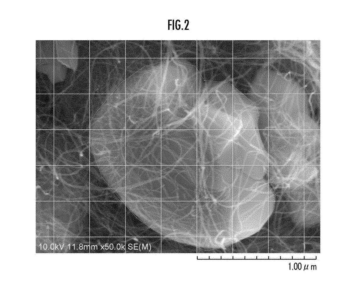
[0038]In the present example, except that carbon nanotubes having a diameter of 10 to 50 nm and a length of 100 to 500 μm produced in accordance with the production method described in Japanese Patent Laid-Open No. 2016-031922, paragraph 0053 were used, a positive electrode-side electrode mixture layer for a secondary battery comprising a positive electrode active material and a conductor of carbon nanotubes in close contact with the surface of the positive electrode active material was obtained in the exactly same manner as in Example 1. A scanning electron micrograph of the surface of the electrode mixture layer of the present example is shown in FIG. 2.

[0039]In the electrode mixture layer of the present example, the number density of the carbon nanotubes determined from the scanning electron micrograph was 10.2 tubes / μm. The results are shown in Table 1.

[0040]Then, a secondary battery was produced in the exactly same manner as in Example 1 except that the electrode mixture layer ...

example 3

[0041]In the present example, except that the carbon nanotubes having a diameter of 8 nm and a length of 200 to 300 μm (manufactured by JEIO Co., Ltd., product name: JENO TUBE 8) were used, a positive electrode-side electrode mixture layer for a secondary battery comprising a positive electrode active material and a conductor of carbon nanotubes in close contact with the surface of the positive electrode active material was obtained in the exactly same manner as in Example 1. A scanning electron micrograph of the surface of the electrode mixture layer of the present example is shown in FIG. 3.

[0042]In the electrode mixture layer of the present example, the number density of the carbon nanotubes determined from the scanning electron micrograph was 13.8 tubes / μm. The results are shown in Table 1.

[0043]Then, a secondary battery was produced in the exactly same manner as in Example 1 except that the electrode mixture layer of the present example was used, and its internal resistance was...


PUM

PropertyMeasurementUnit
diameteraaaaaaaaaa
diameteraaaaaaaaaa
diameteraaaaaaaaaa

Abstract

Provided is an electrode mixture layer capable of reducing internal resistance by use of a carbon nanotube molding. The electrode mixture layer includes an active material and a conductor of carbon nanotubes in close contact with the surface of the active material, and the number density of the carbon nanotubes is 4 tubes/μm or more. The number density is defined as a value obtained by providing measurement lines on a scanning electron microscope image of a surface of the electrode mixture layer at 0.3 μm intervals both longitudinally and laterally, measuring the total number of the carbon nanotubes being in close contact with the surface of the active material and intersecting the measurement lines, and dividing the total number of the carbon nanotubes by the total length of the measurement lines on the active material surface.

Description

BACKGROUND OF THE INVENTIONField of the Invention[0001]The present invention relates to electrode mixture layers.Description of the Related Art[0002]Use of carbon nanotube moldings for electrodes has been contemplated recently. As such electrodes, for example, an electrode also serving as a current collector in which a particulate active material is included in three-dimensional gaps of a three-dimensional fiber complex constituted by a carbon nanotube molding has been known (e.g., see Japanese Patent Laid-Open No. 2016-31922).[0003]The three-dimensional fiber complex is constituted by integrating three-dimensional carbon nanotube fiber bundle skeletons formed by intersection and assembly of a plurality of carbon nanotubes and a conductor composed of carbon nanotubes. In the electrode also serving as a current collector, the active material is supported by and in close contact with the three-dimensional carbon nanotube fiber bundle skeletons or the conductor composed of carbon nanot...

Claims


Application Information

Patent Timeline
Patent Type & Authority Applications(United States)
IPC IPC(8): H01M4/66H01M4/36C01B32/16H01M4/04H01M4/62H01M4/76H01M4/88H01M4/02
CPCH01M4/663H01M4/36C01B32/16H01M4/04H01M4/621H01M4/76H01M4/8875C01B2202/36H01M4/02H01M4/13H01M4/625H01M4/131B82Y30/00Y02E60/50Y02E60/10C01B2202/32C01B2202/20C01B2202/34C01B32/158C01B2202/00
Inventor TOKUNE, TOSHIONISHINUMA, TAKUYAKOMORI, TAKAHIROINOUE, KENSHITANAAMI, KIYOSHINAKAGAWA, TAKASHI
Owner HONDA MOTOR CO LTD
Why Eureka
Try Eureka