Method and apparauts for quantum measurement via mode matched photon conversion

a quantum measurement and mode matching technology, applied in the field of methods, can solve problems such as false alarms, distorted images, and limitations on performance, and achieve the effect of improving system performance and improving per-photon snr

Active Publication Date: 2018-05-31
STEVENS INSTITUTE OF TECHNOLOGY
View PDF0 Cites 18 Cited by
  • Summary
  • Abstract
  • Description
  • Claims
  • Application Information

AI Technical Summary

Benefits of technology

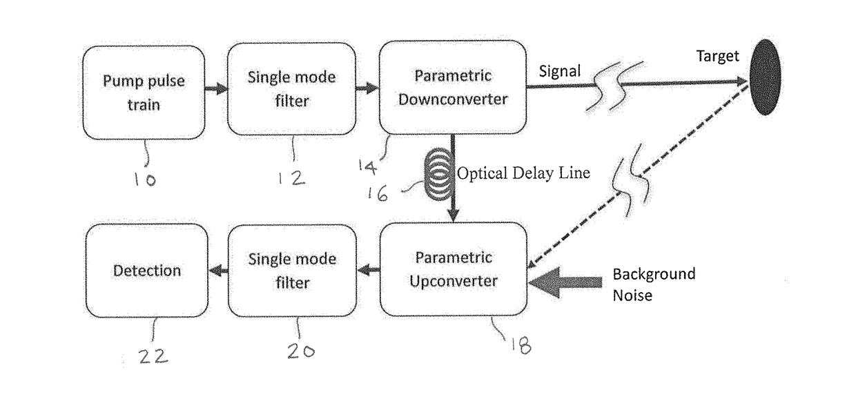
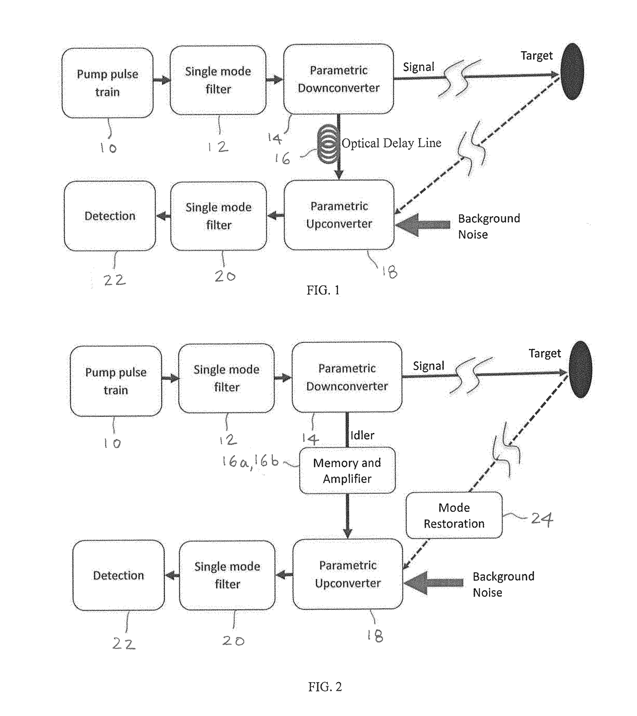
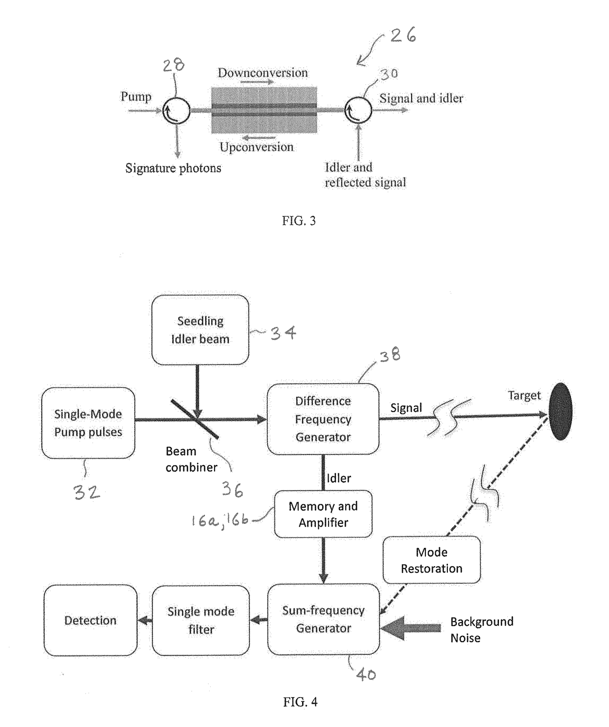
[0011]The disclosed techniques can substantially improve the per-photon SNR similarly to how the QI and its derivative techniques can outperform their classical counterparts. However, unlike those based on QI or use of few-photon entangled states, the disclosed techniques can use instead bright twin beams, each containing many photons per measurement trial, such as those consisting of nanosecond pulses with one-watt peak power and 100 kHz pulse repetition rate. The twin beams do not need to be entangled, which contrasts strongly with those techniques an

Problems solved by technology

In such techniques, however, a major limitation on performance arises from the presence of background noises.
When background noises share the same spectral band and arrival time with the reflected signals, it is difficult, if not impossible, to distinguish them from the information-carrying signals, resulting in false alarms, incorrect object identification, distorted images, and so on.
For many measurement devices, the performance is ultimately limited by the signal to noise ratio (SNR) as detected.
This method of attack is sometimes referred to as “spoofing.” While techniques like pulse shaping and modulating can make the spoofing difficult to

Method used


Image

  • Method and apparauts for quantum measurement via mode matched photon conversion
  • Method and apparauts for quantum measurement via mode matched photon conversion
  • Method and apparauts for quantum measurement via mode matched photon conversion

Examples


Embodiment Construction

[0020]The following disclosure is presented to provide an illustration of the general principles of the present invention and is not meant to limit, in any way, the inventive concepts discussed herein. Moreover, the particular features described in this section can be used in combination with the other described features in each of the multitude of possible permutations and combinations contained herein.

[0021]All terms defined herein should be afforded their broadest possible interpretation, including any implied meanings as dictated by a reading of the specification as well as any words that a person having skill in the art and / or a dictionary, treatise, or similar authority would assign thereto.

[0022]Further, it should be noted that, as recited herein, the singular forms ‘a,’“an,” and “the” include the plural referents unless otherwise stated. Additionally, the terms “comprises” and “comprising” when used herein specify that certain features are present in that embodiment; however...


PUM


Abstract

The present disclosure relates to a generally-applicable measurement technique based on coherent quantum enhancement effects and provides embodiments with nonlinear optics. The technique utilizes parametric nonlinear processes where the information-carrying electromagnetic quanta in a number of electromagnetic modes are converted phase coherently to signature quanta in a single mode or a few modes. The phase coherence means that while the quanta before conversion may have unequal or uncertain phase values across the modes, the signature quanta converted from those different modes have the (near) uniform phase. This can lead to significant increase in the signal to noise ratio in detecting weak signal buried in strong background noise. Applications can be found in remote sensing, ranging, biological imaging, field imaging, target detection and identification, covert communications, and other fields that can benefit from improved signal to noise ratios by using the phase coherent effect.

Description

CROSS-REFERENCE TO RELATED APPLICATION[0001]This application relates to U.S. Provisional Patent Application No. 62 / 427,604 filed Nov. 29, 2016, the entire disclosure of which is incorporated herein by reference.FIELD OF THE INVENTION[0002]The present disclosure relates to method and apparatus adapted for quantum metrology, remote sensing, imaging and covert communications.BACKGROUND OF THE INVENTION[0003]Measurement devices based on the detection of reflected lightwave, microwave, or radio signals can take dynamic, 3D images of remote targets, giving rise to a wealth of robust applications, such as remote sensing, ranging, biological scanning, field imaging, stand-off target identification, and vehicle speed determination. In a typical configuration using radio-wave signals—widely known as radio detection and ranging, or radar—a radio wave beam is created and emitted along a direction of interest. By measuring the reflected radio wave, the presence of an object over distance can be ...

Claims


Application Information

Patent Timeline
IPC IPC(8): G01C3/08G01S17/06H04B10/70
CPCG01C3/08G01S17/06H04B10/70B82Y15/00B82Y20/00G01S17/10G01S17/42
Inventor HUANG, YUPING
Owner STEVENS INSTITUTE OF TECHNOLOGY
Why Eureka
Try Eureka