Light-emitting device package and vehicular light comprising same

a technology of light-emitting devices and vehicular light, which is applied in the direction of semiconductor devices for light sources, light-emitting devices, transportation and packaging, etc., can solve the problems of miniaturization and limitation of modules' own miniaturization, and achieve the effect of reducing the thickness of the adhesive layer, maximizing the reliability of adhesion, and improving the spatial freedom of a structur

Active Publication Date: 2018-06-07
LG INNOTEK CO LTD
View PDF1 Cites 11 Cited by
  • Summary
  • Abstract
  • Description
  • Claims
  • Application Information

AI Technical Summary

Benefits of technology

[0011]According to an embodiment of the present invention, an integrated module in which a module in which a light emitting device and a driving device are mounted on an upper portion and a lower portion of a thermally-conductive substrate is pressed by an autoclave, thereby improving a degree of spatial freedom of a structure.
[0012]In addition, according to an embodiment of the present invention, a light emitting device package capable of realizing bonding reliability and thinning may be implemented in a bending structure of a thermally-conductive substrate having a bending structure, thereby overcoming a space limitation.
[0013]Further, according to an embodiment of the present invention, an autoclave method may be applied based on a flexible printed circuit board having ductility of a film material, thereby remarkably reducing a thickness of a adhesive layer and maximizing reliability of adhesion.
[0014]Furthermore, according to an embodiment of the present invention, a heat sink may be directly attached between an LED array module and an LED drive module, thereby increasing a heat dissipation characteristic.

Problems solved by technology

However, in the case of a printed circuit board on which an LED is mounted, a size of the printed circuit board is increased in consideration of a driving device necessary for driving the LED and the LED's own heat dissipation characteristic, which leads to a limitation in a module's own miniaturization.
In addition, a structure of a heat sink for dissipating heat from a device having a large amount of heat such as an LED is essentially arranged, which causes a problem for the trend of miniaturization described above.

Method used


Image

  • Light-emitting device package and vehicular light comprising same
  • Light-emitting device package and vehicular light comprising same
  • Light-emitting device package and vehicular light comprising same

Examples


Embodiment Construction

[0027]Hereinafter, a configuration and an operation according to the present invention will be described in detail with reference to accompanying drawings. In the following description with reference to the accompanying drawings, the same reference numerals denote the same components regardless of the reference numerals, and a duplicate description thereof will be omitted. The terms first, second, and the like may be used to describe various components, but the components should not be limited by the terms. The terms are used only for the purpose of distinguishing one component from another.

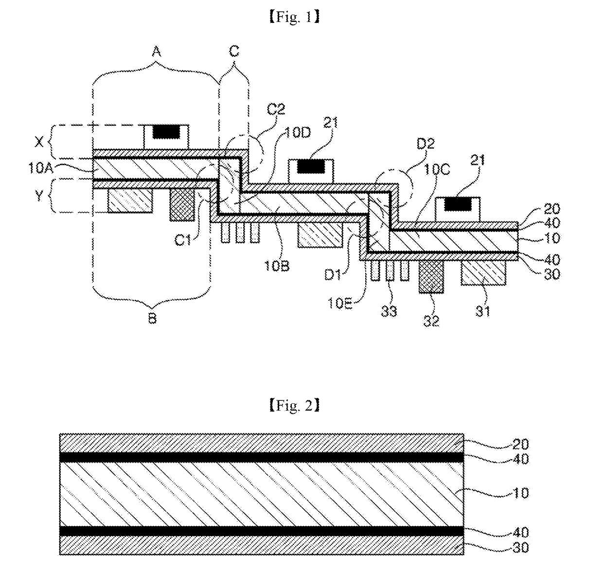
[0028]FIG. 1 is a cross-sectional view schematically illustrating a light emitting device package according to an embodiment of the present invention. FIG. 2 is a cross-sectional view of a main part of FIG. 1.

[0029]Referring to FIGS. 1 and 2, according to an embodiment of the present invention, a light emitting device package may be configured to include a light emitting device module X including...


PUM


Abstract

According to an embodiment, a light emitting device package includes: a thermally-conductive substrate having at least two mounting regions on which chips are mounted and at least one bending region; a light emitting device module including a light emitting device arranged on one surface of the mounting region; and a driving device module including a driving unit arranged on the other surface opposite to the one surface of the mounting region.

Description

TECHNICAL FIELD[0001]An embodiment of the present invention relates to a light emitting device package, and more particularly, to a light emitting device package capable of securing a degree of design freedom of a printed circuit board while promoting a heat dissipation characteristic and a vehicle light including the same.BACKGROUND ART[0002]In general, a light emitting diode (hereinafter referred to as LED) is basically composed of a junction of a p-type and an n-type semiconductor. In addition, the LED is a kind of photoelectronic device that emits energy corresponding to a bandgap of a semiconductor in a form of light by the combination of electrons and holes as a voltage is applied.[0003]This LED is widely used in a range of applications such as a high luminance light source for flash, a backlight for a liquid crystal display (LCD) used in a portable electronic product such as a mobile phone, a camcorder, a digital camera, and a PDA, a light source for a electronic signboard, a...

Claims


Application Information

Patent Timeline
Patent Type & Authority Applications(United States)
IPC IPC(8): F21S41/19F21S43/19F21V29/89H05B33/08F21S43/20F21S43/14F21S41/141F21S41/20F21S45/47F21W107/00H05B44/00
CPCF21Y2115/10F21S41/192F21S43/195F21V29/89H05B33/0815H05B33/0812F21S43/26F21S43/14F21S41/141F21S41/285F21S45/47H05B33/089H05B33/0842F21S43/19F21S43/15H05B45/395H05B45/00H05B45/3725F21V29/70F21V5/04F21V23/003H05K1/189
Inventor LEE, KANG SUKOH, NAM SEOKCHO, YOUNG JUN
Owner LG INNOTEK CO LTD
Why Eureka
Try Eureka