
Light emitting device and manufacturing method thereof

a technology of light-emitting devices and manufacturing methods, which is applied in the direction of semiconductor devices, semiconductor/solid-state device details, electrical apparatus, etc., can solve the problems of uniform electrical current supply, increase of manufacturing costs, and worsening of so as to improve the light condensation property of elements, improve the light-emitting efficiency of elements, and increase manufacturing costs

Active Publication Date: 2018-06-07
CITIZEN ELECTRONICS CO LTD +1
View PDF12 Cites 2 Cited by
  • Summary
  • Abstract
  • Description
  • Claims
  • Application Information

AI Technical Summary

Benefits of technology

The light-emitting device described in the patent can produce light that closely matches its designed color value, even when multiple light-emitting elements are used. This is achieved by using a resin that contains a phosphor and is excited by the light emitted from the elements. The technical effect of this invention is to create a light source that more accurately matches its designed color value, even when multiple light-emitting elements are used.

Problems solved by technology

However, when the emission region is achieved by using only one light-emitting element, a large element is necessarily used to secure desired light emission intensity, leading to disadvantages such as the elevation of manufacturing costs and non-uniform electrical current supply to the light-emitting element, which worsens the light emission efficiency of the element.
The traveling distance of light in the phosphor layer varies depending on the position and direction of the emission from the light-emitting elements, thereby causing the intensity variation of light having a color corresponding to the phosphor, resulting in difficulty in adjusting the actual hue of the emitted light to a designed hue value.

Method used


Image

  • Light emitting device and manufacturing method thereof
  • Light emitting device and manufacturing method thereof
  • Light emitting device and manufacturing method thereof

Examples


Embodiment Construction

[0032]Hereinafter, with reference to the accompanying drawings, a light-emitting device and a manufacturing method thereof will be explained in detail. However, it should be noted that the present invention is not limited to the drawings or the embodiments described below.

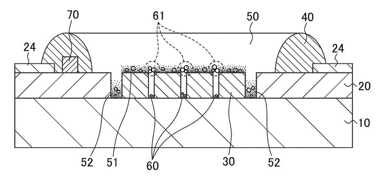
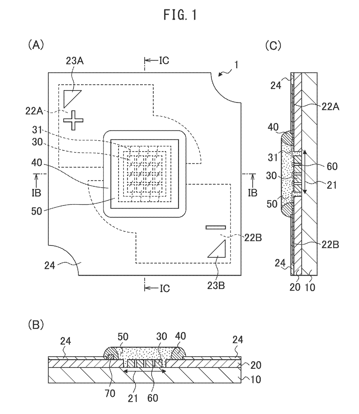
[0033]FIG. 1(A) to FIG. 1(C) are a top view and cross-sectional views of a light-emitting device 1. FIG. 1(A) is a top view of the light-emitting device 1 as a completed product, FIG. 1(B) is a cross-sectional view along the line IB-IB in FIG. 1(A), and FIG. 1(C) is a cross-sectional view along the line IC-IC in FIG. 1(A). The light-emitting device 1 includes LED elements as light-emitting elements, and is used for various illumination apparatuses such as LEDs for illumination and LED light bulbs. The light-emitting device 1 is provided with a mount board 10, a circuit board 20, LED elements 30, a resin frame 40, a seal resin 50, and a Zener diode 70, as major components.

[0034]The mount board 10 is, for example, an...


PUM


Abstract

A light-emitting device and a manufacturing method thereof are provided, which device yields light exhibiting an actual hue with a deviation reduced as much as possible from a designed hue value, wherein the light is a mixture of light emitted from densely-mounted light-emitting elements and excited light from a phosphor contained in a resin sealing the light-emitting elements. The light-emitting device includes a board, light-emitting elements mounted densely on the board so that light-emitting surfaces thereof face opposite to the board, and a seal resin containing a plurality of different phosphors and covering all of the light-emitting elements, wherein the phosphors are excited by light from the light-emitting elements and deposited on upper surfaces of the light-emitting elements. A space between adjacent light-emitting elements has a length of 5 μm or more and 120% or less of a median diameter D50 of a phosphor which has the largest average particle size of the phosphors.

Description

TECHNICAL FIELD[0001]The present invention relates to a light-emitting device and a manufacturing method thereof.BACKGROUND ART[0002]There are known COB (Chip On Board) light-emitting devices provided with light-emitting elements such as LED (light-emitting diode) elements mounted on a general purpose board such as a ceramic board and a metal board. In such light-emitting devices, LED elements emitting light such as blue light are sealed with a resin containing a phosphor, which is excited by the light from the LED elements to yield light that is mixed therewith to provide light such as white light according to an application.[0003]For example, Patent Literature 1 describes a light-emitting diode provided with a heat dissipation support with high thermal conductivity having a mount surface for die bonding, a circuit board which is placed on the heat dissipation support and has not only a hole for exposing a region of the mount surface but also overhang regions overhanging the perime...

Claims


Application Information

Patent Timeline
Patent Type & Authority Applications(United States)
IPC IPC(8): H01L33/50H01L33/56H01L33/58H01L25/075
CPCH01L33/507H01L33/56H01L33/58H01L25/0753H01L2933/005H01L2933/0041H01L25/167H01L29/866H01L27/0248H01L2924/181H01L2224/48137H01L23/60H01L33/508H01L33/60H01L2924/00012H01L33/48H01L33/50
Inventor IMAI, SADATOWATANABE, MASAHIDEISHII, HIROHIKOHIRASAWA, KOKI
Owner CITIZEN ELECTRONICS CO LTD
Learn More