
A three-port direct current converter

a converter and three-port technology, applied in the direction of electric variable regulation, process and machine control, instruments, etc., can solve the problems of low power density and efficiency, intermittent energy source nature, etc., and achieve the effect of size, price and weight of the converter

Active Publication Date: 2018-06-07
DANMARKS TEKNISKE UNIV
View PDF3 Cites 23 Cited by
  • Summary
  • Abstract
  • Description
  • Claims
  • Application Information

AI Technical Summary

Benefits of technology

The patent proposes a three-port converter that can operate in two different power flow configurations. This converter can be used in LED lighting applications where there is a need to match the current across multiple LEDs. The converter provides a high step-up, which is useful for driving multiple LEDs connected in series. In one configuration, the converter operates as a buck converter to charge a battery, and in the other configuration, it operates as a boost converter to drive the load. Compared to conventional converters, the proposed design with a single magnetic component is smaller, lighter, and less expensive.

Problems solved by technology

However, the main drawback is that the energy source is intermittent in nature since it strongly depends on the weather conditions.
However, the disadvantages are low power density and efficiency due to multiple conversions stages.

Method used


Image

  • A three-port direct current converter
  • A three-port direct current converter
  • A three-port direct current converter

Examples


examples

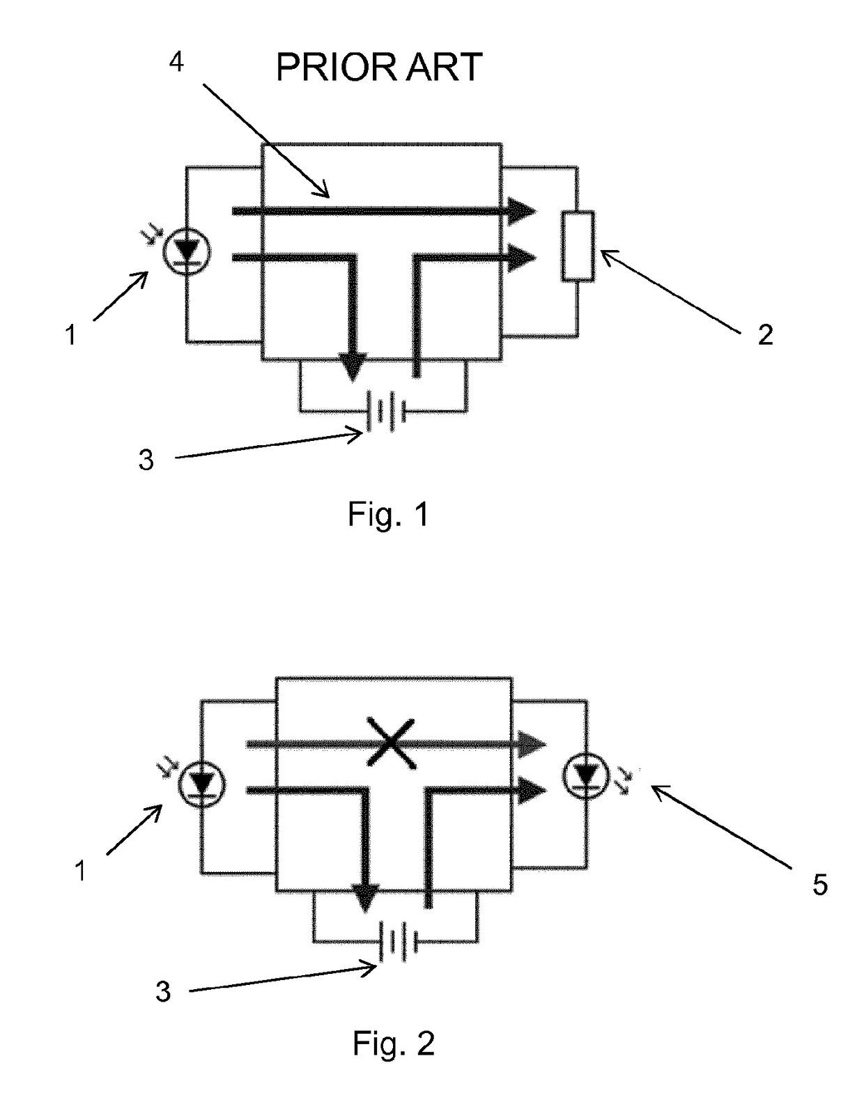
[0044]FIG. 1 shows a conventional three-port converter having an input power source 1, a battery 3 and a load 2. The design of the three-port converter is complex and requires a large number of electrical components. In the conventional three-port converter there is a direct power flow 4 from the power input to the load.

[0045]FIG. 2 is a conceptual drawing of a three-port converter according to the present invention having an input power source 1, a battery 3 and a light-emitting diode 5, which constitutes the load, wherein the three-port direct current converter is configured to operate in two mutually exclusive power flow configurations. This design corresponds to an electrical circuit having a primary side circuit comprising a connection between the at least one input direct current source and the at least one storage battery, the primary side circuit configured for operating as a buck converter, and having a secondary side circuit comprising a connection between the at least one...


PUM


Abstract

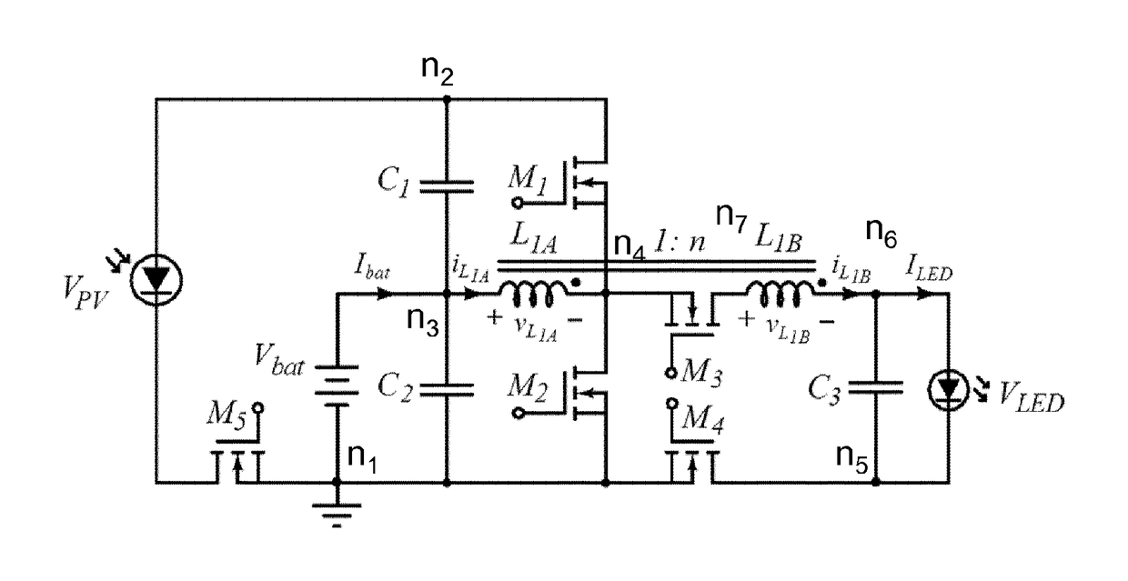
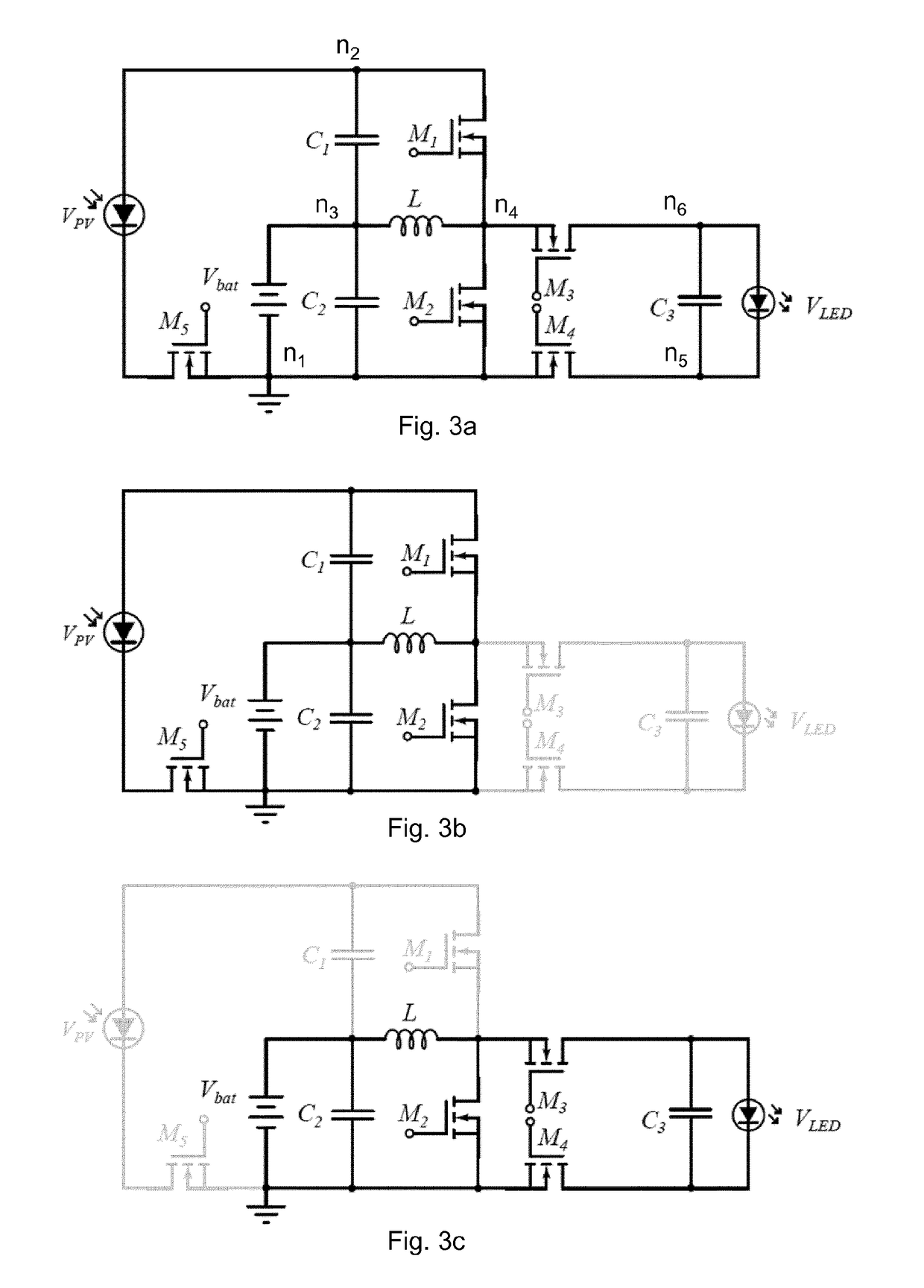
The three-port direct current converter comprising: at least one input direct current source; at least one storage battery; a primary side circuit; a secondary side circuit; a first single magnetic component shared by the primary side circuit and the secondary side circuit, wherein the primary side circuit comprises a connection between the at least one input direct current source and the at least one storage battery, the primary side circuit configured for operating as a buck converter; a second magnetic component serially coupled to the first single magnetic component, wherein the first and second magnetic components are configured to perform a voltage step-up, wherein the secondary side circuit comprises a connection between the at least one storage battery and at least one load, the secondary side configured for operating as a tapped boost converter; wherein the three-port direct current converter is configured to operate in two mutually exclusive power flow configurations.

Description

FIELD OF THE INVENTION[0001]The invention relates to a three-port direct current converter, operating in two mutually exclusive power flow configurations, sharing a magnetic component.BACKGROUND OF INVENTION[0002]Solar energy is one of the fastest growing renewable energy sources mainly because sunlight is the most abundant source of energy and is unlimited, clean and free. The major advantage of solar energy is the transformation of energy with zero carbon dioxide (CO2) emissions. However, the main drawback is that the energy source is intermittent in nature since it strongly depends on the weather conditions. In order to overcome this limitation, energy storage elements are often required in order to provide a constant power source.[0003]Multi-input converters (MIC) topologies address the issue of interconnecting several energy sources with a single power converter. The conventional approach to implement multi-input power systems is to interconnect the elements using different ser...

Claims


Application Information

Patent Timeline
IPC IPC(8): H02M3/158H02J7/35H02M1/00H05B44/00
CPCH02M3/1582H02J7/35H02M1/00H02M2001/0064H02M2001/0009Y02B20/30H05B45/38H05B45/375H02M1/0067H02M1/0064H02M1/009H02M1/0009
Inventor ALBERT, MARIA DEL CARMEN MIRA
Owner DANMARKS TEKNISKE UNIV
Learn More