Vehicle with suspension force decoupling system

a technology of suspension and decoupling system, which is applied in the direction of resilient suspension, vehicle springs, vehicle components, etc., can solve the problems of grip fluctuations on the road surface, and achieve the effect of improving the performance of existing corner suspension systems and improving overall ride comfor

Active Publication Date: 2018-06-14
GM GLOBAL TECH OPERATIONS LLC
View PDF1 Cites 20 Cited by
  • Summary
  • Abstract
  • Description
  • Claims
  • Application Information

AI Technical Summary

Benefits of technology

[0004]The term “wheel hop” as used herein refers to a phenomenon in which the road wheels may tend to shake or vibrate due to effects of vertical oscillation of the unsprung mass of the suspension system, i.e., the mass of the road wheel and suspension arm. Such vertical movement may cause grip fluctuations to occur at the road surface. The system disclosed herein is thus intended to improve performance of existing corner suspension systems by enabling targeted force decoupling in a predetermined frequency range, such as the frequency range corresponding to the wheel hop frequency.
[0005]By using a suspension actuator as a free body as set forth herein, the actuator force may be effectively decoupled from vertical body accelerations so as to improve overall ride comfort across all road vibration frequencies. Suspension performance may therefore be “tuned” via proper selection of the masses of the suspension actuator and the compliance characteristics of the coil springs or other mechanically compliant elements described herein. Unlike traditional rubber bushing configurations providing passive mechanical compliance levels of more than 500 N / mm, the present approach purposefully uses mechanically compliant elements providing a much lower or “softer” compliance level, e.g., 20 N / mm-50 N / mm, so that resonant frequencies experienced from road vibrations approach the vehicle's wheel hop frequency, typically on the order of about 9-13 hertz (Hz).

Problems solved by technology

Such vertical movement may cause grip fluctuations to occur at the road surface.

Method used


Image

  • Vehicle with suspension force decoupling system
  • Vehicle with suspension force decoupling system
  • Vehicle with suspension force decoupling system

Examples


Embodiment Construction

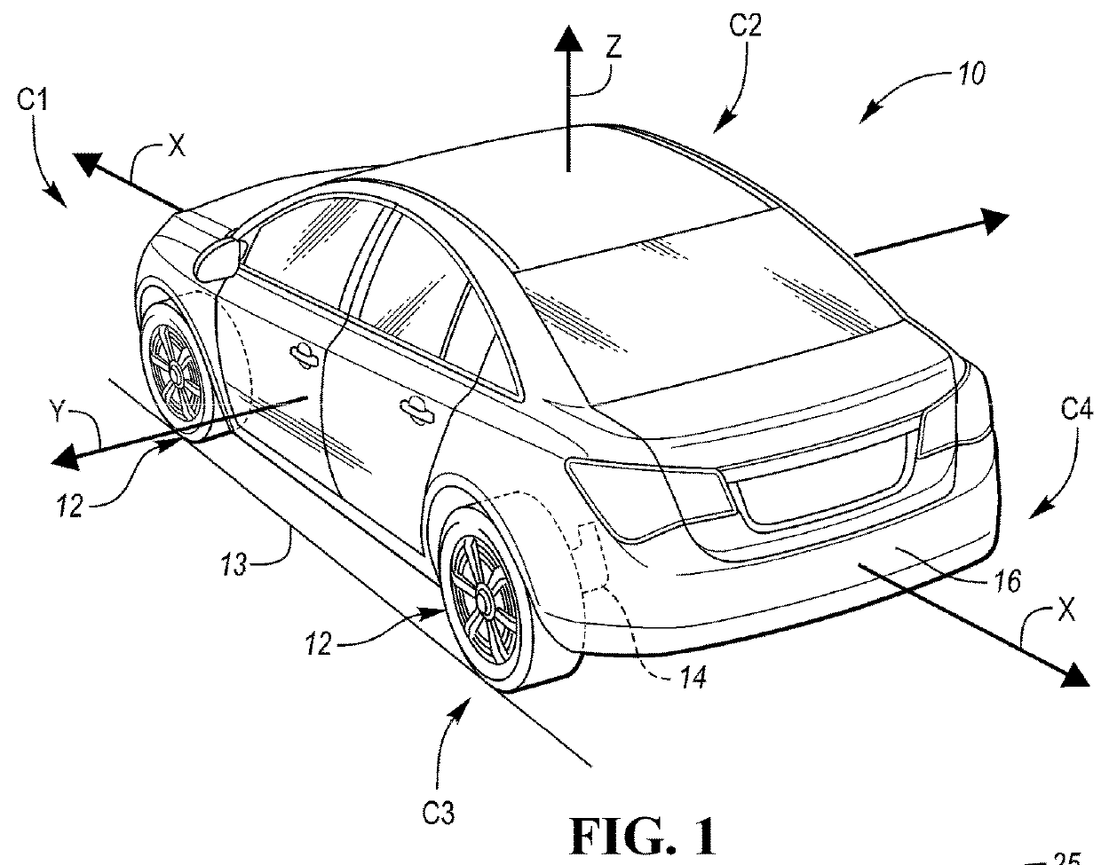
[0014]Referring to the drawings, wherein like reference numbers refer to like components, FIG. 1 provides a schematic view illustration of an example vehicle 10 having a plurality of road wheels 12 in rolling contact with a road surface 13. The vehicle 10 includes a vehicle body 16 arranged with respect to a vertical (Z), longitudinal (X), and transverse / lateral (Y) axis in an example XYZ Cartesian coordinate system. In the example embodiment of FIG. 1, the vehicle 10 has four corners C1, C2, C3, and C4. Each of the road wheels 12 is disposed at one of the corners C1-C4, and is operatively connected to a suspension force decoupling system 14 as described herein. Although four road wheels 12 and thus four corners C1-C4 are shown in FIG. 1, a vehicle 10 having fewer or more road wheels 12 may be envisioned within the scope of the present disclosure.

[0015]Although omitted from the Figures for illustrative simplicity, the vehicle 10 also includes a powerplant configured to generate a dr...


PUM


Abstract

A vehicle includes a vehicle body, a road wheel, and a suspension corner connecting the road wheel to the vehicle body. The suspension corner includes a suspension arm connected to the road wheel and to the vehicle body, and also includes a suspension force decoupling system disposed on an axis extending between the suspension arm and the vehicle body. The suspension force decoupling system includes an actuator having an actuator mass arranged on the axis that is configured to output an actuator force in opposite directions along the axis in response to an actuator control signal. The system also includes a compliant element connected along the axis to the actuator mass and one of the body and the suspension arm, and providing a predetermined level of mechanical compliance. A controller determines and generates the actuator force in response to a threshold acceleration of the vehicle body.

Description

INTRODUCTION[0001]Suspension systems of contemporary vehicles and other wheeled mobile platforms may be used at the corners of the vehicle's body or chassis. Corner suspension systems generally include springs, shock absorbers, and various linkages that connect the vehicle body to the vehicle's road wheels. Because a majority of the forces acting on the vehicle body are transmitted through contact patches between the road surface and the tires of the road wheels, one of the main objectives of a corner suspension system is to maintain contact or “grip” between the road wheels and the road surface.[0002]Vehicle suspension systems contribute to ride comfort and isolation from road noise, bumps, and vibration, as well as road-holding / handling and braking performance. Because these objectives are generally at odds with each other, the tuning or configuration of a given corner suspension system involves finding an optimal comfort-grip tradeoff appropriate to the vehicle's intended purpose...

Claims


Application Information

Patent Timeline
Patent Type & Authority Applications(United States)
IPC IPC(8): B60G17/0165B60G11/16B60G7/00B60G17/016B60G17/019B60G17/02B60G17/015
CPCB60G17/0165B60G2400/821B60G7/006B60G17/0164B60G17/0162B60G17/01908B60G17/021B60G17/0155B60G17/0157B60G2200/14B60G2202/12B60G2202/422B60G2202/413B60G2202/412B60G2202/442B60G2204/1244B60G2204/127B60G2204/143B60G2204/62B60G2400/102B60G2400/104B60G2400/106B60G11/16B60G17/015
Inventor TRANGBAEK, KLAUS
Owner GM GLOBAL TECH OPERATIONS LLC
Why Eureka
Try Eureka