Distallation device (amended)

a technology of distillation device and distillation chamber, which is applied in the field of distillation device, can solve the problems of large increase in equipment cost, operating cost and equipment cost, and relative difficulty in separating acetone and methanol, and achieve the effects of reducing methanol content, facilitating methanol separation, and prolonging catalyst li

Active Publication Date: 2018-06-21
LG CHEM LTD
View PDF7 Cites 1 Cited by
  • Summary
  • Abstract
  • Description
  • Claims
  • Application Information

AI Technical Summary

Benefits of technology

[0107]According to the distillation device of the present application, when a feedstock containing acetone and methanol is separated using a distillation device, a methanol removal distillation column may be located at a position for easily separating methanol to solve a problem due to accumulation of methanol in the process and to lower the methanol content in the acetone product, and thus the lifetime of catalysts can be extended, and moreover, methanol can

Problems solved by technology

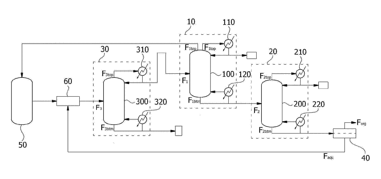
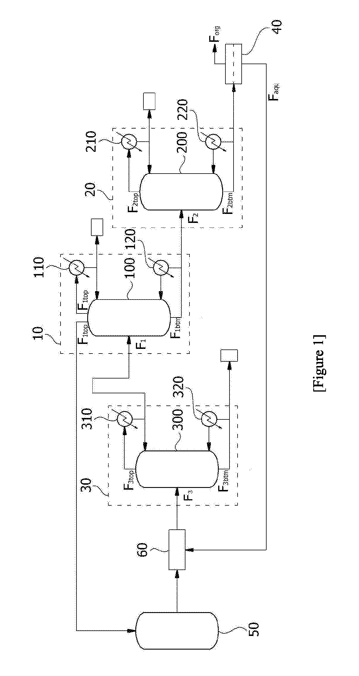
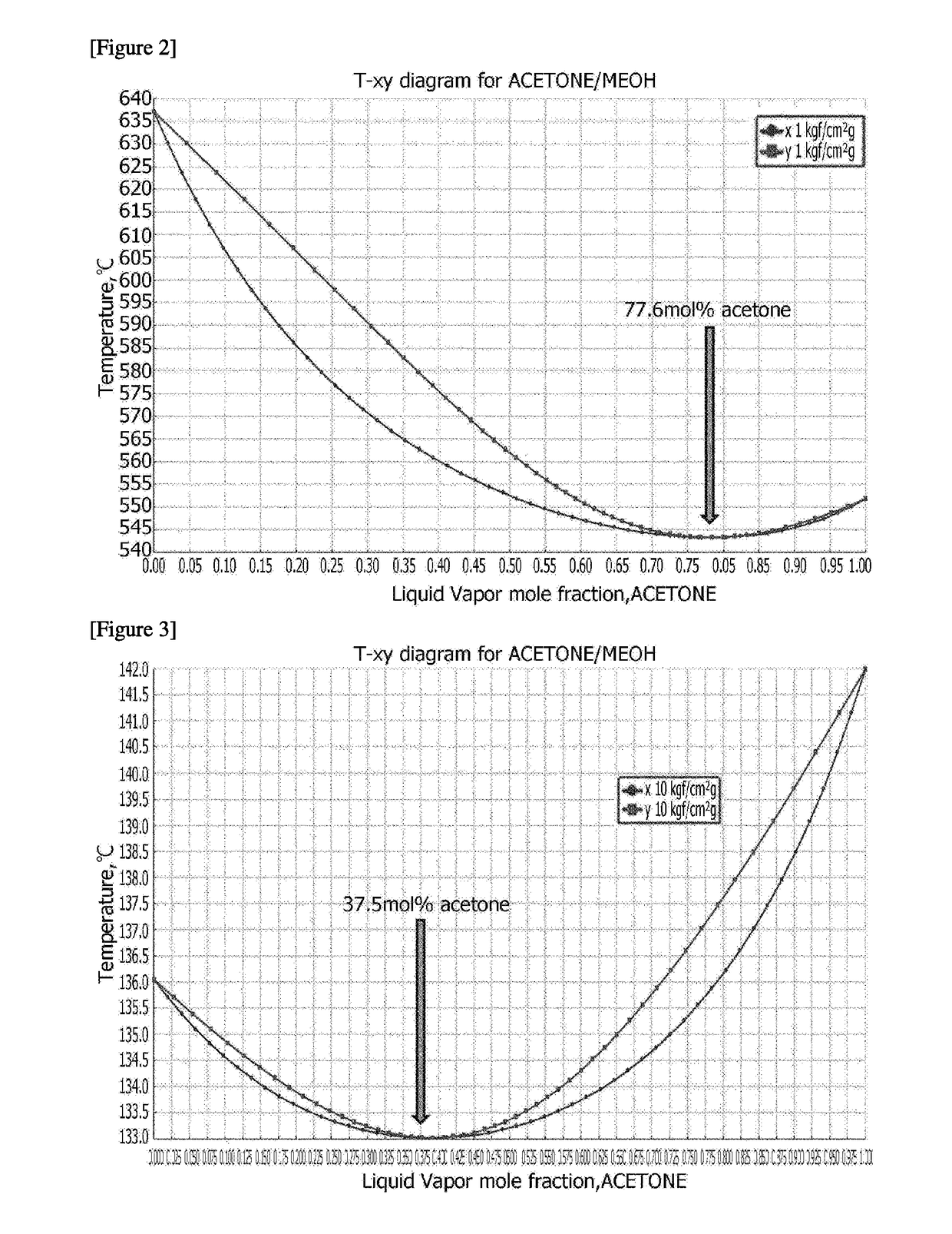
Meanwhile, it has been known that it is relatively difficult to separate acetone and methanol, and conventionally, methods have been used, such as a pressure swing distillation process (PSD) for separating highly pure methanol at a pressure of about 1 kgf/cm2g through change of an operating pressure and separating highly pure acetone at a pressure of 10 kgf/cm2g or an extractive distillation process for separating methanol and a

Method used


Image

  • Distallation device (amended)
  • Distallation device (amended)
  • Distallation device (amended)

Examples


example 1

[0130]Acetone and methanol were separated using the distillation device of FIG. 8.

[0131]Specifically, a feedstock containing 55% by weight of acetone, 22% by weight of cumene, 4% by weight of alpha-methylstyrene, 0.03% by weight of methanol, and 0.14% by weight of a high boiling point component was introduced into the first distillation column having a number of theoretical stages of 65 at a temperature of 88° C. and a flow rate of 43,000 kg / hr.

[0132]The first top flow discharged from the top region of the first distillation column passed through the first condenser and a portion was refluxed to the top region of the first distillation column. The remaining portion of the first top flow was separated and stored as a product comprising 99.8% by weight of acetone and 0.02% by weight of methanol, and the first bottom flow discharged from the bottom region of the first distillation column passed through the first reboiler, and a portion was refluxed to the bottom region of the first dis...

example 2

[0138]Acetone and methanol were separated by the same method as Example 1, except that the operating conditions of the second distillation column were changed as in Table 1 below.

[0139]In the case of separating acetone and methanol using the distillation device of Example 2, the used amount of energy in first and second reboilers and the removal rate of methanol were shown in Table 1 below.

example 3

[0140]Acetone and methanol were separated using the distillation device of FIG. 9.

[0141]Specifically, a feedstock containing 55% by weight of acetone, 22% by weight of cumene, 4% by weight of alpha-methylstyrene, 0.03% by weight of methanol, and 0.14% by weight of a high boiling point component was introduced into the first distillation column having a number of theoretical stages of 65 at a temperature of 88° C. and a flow rate of 43,000 kg / hr.

[0142]The first top flow discharged from the top region of the first distillation column passed through the first condenser and a portion was refluxed to the top region of the first distillation column. The remaining portion of the first top flow was separated and stored as a product comprising 99.8% by weight of acetone and 0.02% by weight of methanol, and the first bottom flow discharged from the bottom region of the first distillation column passed through the first reboiler, and a portion was refluxed to the bottom region of the first dis...


PUM

PropertyMeasurementUnit
Temperatureaaaaaaaaaa

Abstract

The present application relates to a distillation device. When a feedstock containing acetone and methanol is separated using a distillation device according to the present application, a methanol removal distillation column may be located at a position for easily separating methanol to solve a problem due to accumulation of methanol in the process and to lower the methanol content in the acetone product, and thus the lifetime of catalysts can be extended, and moreover, methanol can be removed with good efficiency from a flow of the lower part of the distillation column obtaining the final acetone product by using only the conventional phase separator and one methanol removal distillation column further installed, so that the acetone product obtained from the upper part of the distillation column obtaining the acetone product can be obtained in high purity and the operating cost and the equipment cost of equipments can be greatly reduced.

Description

TECHNICAL FIELD[0001]The present application relates to a distillation device.[0002]The present application claims the benefit of priority relative to Korean Patent Application No. 10-2015-0094491 dated Jul. 2, 2015, the disclosure of which is herein incorporated by reference in its entirety.BACKGROUND ART[0003]Phenol is used in various fields as feedstocks of various synthetic resins such as polycarbonate resin and epoxy resin, including phenol resin, or feedstocks in the pharmaceutical industry, and feedstocks of detergents, such as nonylphenol, or various color paints.[0004]Methods for producing phenol from cumene are well known. For example, the cumene is oxidized using a gas containing oxygen to form cumene hydroperoxide, which is again decomposed under an acidic catalyst, thereby resulting in phenol and acetone.[0005]In the process of generating phenol as above, various side reactions occur at the same time. For example, a trace amount of methanol is generated in the reaction ...

Claims


Application Information

Patent Timeline
IPC IPC(8): B01D3/14B01D3/36
CPCB01D3/143B01D3/36B01D3/141C07C37/08C07C45/53C07C45/84C07C39/04C07C49/08B01D3/32
Inventor CHOO, YEON UKLEE, SUNG KYUKIM, TAE WOOPARK, JONG SUHSHIN, JOON HO
Owner LG CHEM LTD
Why Eureka
Try Eureka